This is how I used a neon sign transformer to create my own classic sci-fi prop the Jacobs Ladder. A Jacobs Ladder is nothing more than two vertical wires attached to a very high voltage. The wires which form the ladder are close together at the base but diverge as they go up. When switched on an electric arc forms at the base of the wires. The arc heats the air above it and in doing so forms an easier path for the electricity to take. The arc moves upwards continually heating the air above itself and rising to take the easier path until eventually the arc reaches the end of the wires and leaps into the air. Once free of the wires it dies but a new arc starts again at the bottom of the ladder. The arc itself moves with a very distinctive buzzing noise. These devices are most usually seen in old sci-fi and horror films and the houses of strange people.
The transformer used is a special type of transformer used to drive neon signs. The signs use a gas filled tube that needs a high voltage to excite the gas in the tube causing it to glow. The tubes once glowing are what is called a negative resistance device. They will try to draw more and more current as they glow more and more brightly. A neon sign transformer is specially designed to be self current limiting so that it can drive tubes without destroying the tube or itself. The transformer I use is rated for an output voltage of 12000 volts AC at 30 mA of current.
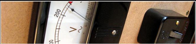
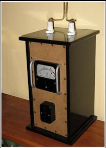
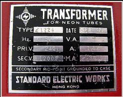
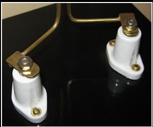
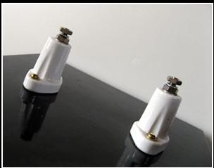
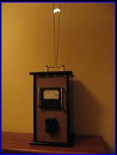
The Jacobs Ladder device is really just a neon sign transformer in a box with a switch, a voltage meter and the two wires that form the ladder mounted on top of the box attached to insulated mounting posts. The box I made from MDF. It is glued and nailed together with internal fillets for extra strength. The transformer is very heavy so the box must be robust. I paint the outside of the box with many layers of the cheapest varnish I can buy to seal the wood. I then sand the box and finish it off with several coats of gloss black spray paint. The front panel is made from Masonite. Mounted to it is a 0-300VAC meter and a Bakelite switch. I used many screws around the edge of the front panel to hold it in place because somebody once told me I might have one loose. The bottom of the box has a piece of felt glued to it to stop it scratching whatever it is sitting on. The mains cable runs out of a hole in the back of the box. I have a fuse wired into the transformer primary circuit inside the box.
The insulators I am using are made from porcelain and they are used to isolate the high voltage terminals from anything conductive. These are screwed into the top of the box. Inside the box heavy duty wires are attached from the high voltage terminals on the transformer to the inside of the porcelain insulators. I use several layers of clear plastic tube over the wires inside the box as extra electrical insulation. The ladder wires I use are made from brass and are 3 mm diameter and they rise about 820 mm above the insulators.  The bottom of the wires are bent out at 90 degrees and the ends are soldered to small brass plates.
The plate has a hole in it to allow it to be bolted to the top of one of the insulators and it also allows it to be rotated allowing me to set the gap at the bottom of the wires. The spacing is critical since you need to ensure an arc will always strike at the base of the wires. I found the best shape for the wires isn't the normal V shape with perfectly straight wires. I found my ladder works better if the wires are not straight but rather curved in slightly. The wires do end up vibrating quite a lot due to the influence of the arc and this makes the movement of the arc less uniform and the display more random.
WARNING: The device described here is very dangerous. It uses both mains and high voltages and dangerous currents. Coming into contact with the ladder while operating is potentially fatal!
Here is a small (1.8MB) video of the Jacobs Ladder working.
Jacobs Ladder film
Simon Jansen 2006
www.asciimation.co.nz