Page 14
Page 1 - Page 2 - Page 3 - Page 4 - Page 5 - Page 6 - Page 7 - Page 8 - Page 9 - Page 10
Page 11 - Page 12 - Page 13 - Page 14 - Page 15 - Page 16 - Page 17 - Page 18 - Page 19
Page 20 - Page 21 - Page 22 - Page 23 - Page 24 - Page 25
February 2009
A long time between updates sorry (I have fans wondering what I am doing apparently)! I have actually done
a lot on the car but have been slack at updating the site about it.
Firstly I decided I should go out and buy a lot of the expensive, finishing things I will need. So I
splashed out on carpets, trim panels and new seats. Luckily I did so when the dollar still had some
value in it! The carpet was from Moss and is black. The trim is from a 1970 spec. car since I like
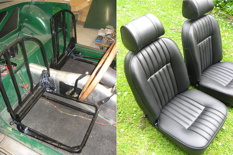
the plain, black finish. The seats are somewhat special. I had Neville, my parts guy, do them for me.
I stripped and repainted my old seat frames then sent them to Neville who fitted their own, full
black leather covers. They are slightly modified to normal ones to give the seats a little more
shape to them. They are all leather instead of leather with a vinyl back to them too. They came out
looking great and are very firm and comfortable. I had to get some second hand hinge covers and reclining
levers off eBay. Replacements are available but expensive and second hand ones usually clean up fine.
Needless to say I fitted all new foams and diaphram too. I think Neville mods the foams slightly. I also
needed to buy new headrests as mine were missing when I got the car.
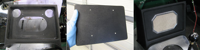
Another little job was the radio console. I always loved the 1970 plain centre console. Luckily someone in
the local MG car club was selling a load of parts off. One of them was this used console. I do have one
(actually two I think?) but they are both cracked. This is a common fault on these second hand. I bought
this one which isn't craced but it had been haced by someone to have two gauges in it. The holes were
very roughly done of course. To fix this I cut a piece of aluminium the right size to fit into the
console and cover all the holes. Since I am not having a speaker behind there I covered over the large
speaker hole too. Over the aluminium I glued a piece of plastic sheet I got off the cover of a notes
binder. This was the kind with clear plastic sleeves in it that you get for a few dollars. The black
cover has the same textured finish as the console plastic. This is all held in place by the grill
surround. Not original of course but a neat way of fixing the damage.
Ah, and now a job that sounds simple but that takes hours. I fitted the doors (and boot and bonnet). This is
major pain in the neck to get right. Even if your car hasn't been in any accidents I imagine. Mine was a
nightmare dure to the car being dinged in the past, having non original front wings and having had the
doors repaired badly in the past. I did the best I could. First you need to get the front wings right.
There is a lot of adjustment here so it shouldn't be too bad getting them in the right place. Once the
wings are in place you can fit the doors. There are quite a number of adjustments here to get right. The
hinge position on the A pillar can move up and down and left and right. I also needed in and out as it
happens. The door on the hinges can move forward and backwards and rotate in the gap. You set how far
in or out the door is relative to the side of the car with where the hinges attach to the A frame. The
leading edge of the door should be flush with the training edge of the wing. You also adjust the up and
down position of the door this way.
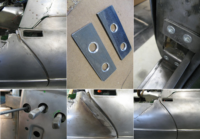
Next you can adjust the fit of the door in the gap by adjusting where the hinge attaches to the door
shell. You can slide the door forwards and backwards to get the gaps even around the edge of the door
opening. Here I found a problem. I couldn't move the door back far enough to get even gaps. To fix this
I made some 3mm shims from steel that I placed between the hinge and the A pillar (yes, meaning I had to
all that again)! That allowed me to get the gaps mostly even. Of course they never will be is the shape
of the door is different ot the shape of the door hole! To fix that you need to get crafty. What I did
was weld around the edges wehre the gap was too small. I used a copper plate under the edge then weld
along the edge over the plate. The plate gives a nice smooth surface to the back of the weld (which
won't stick to the copper). Then you can grind and sand the edge to get the shape you want. I will need
a slight skim of filler over the edge but that is no big deal.
One the door is the same shape as the hole (but smaller of course!) you can line the door up. Even then
there can be problems as the door can have a twist to it. To fix this I bolted a section of steel to the
frame and twisted it until it fitted I believe they used a similar technique in the factory!
Then there are only abut 600 more minor adjustments and you end up with a door that fits nicely in the
gap it is supposed to. Obviously all this involves putting the doors on and off countless times. If you
use the original pozi drive screws this is a major paint in the nec and the screws will end up totally
buggered even if you do use the right pozi bit. My advice here is to replace the screws with countersunk
allen head screws. These you can do up quickly and easily and not have to worry about messing up the
heads. You can also do them up nice and tight by hand as well.
Another tip is how to get the screws lined up. I use two nail punches. Each hinge has three screws. You
slide the door onto the hinge then line a punch with two of the holes in a hinge. The punches are tapered
so they are easy to get started then the taper pulls the hinge holes into position so the third hole
is automatically lined up allowing you to get that first screw in. The others are easy after that.
Please note: I did not do the horrible patch around the crack of door on this door! I got it like that.
It looks bloody awful, and I would never do such a rough job but it is sound so I left well enough alone
there. It all gets covered in filler anyway I guess.
Fitting the boot lid is a similar nightmare. Basically it is similar to fitting the doors. Most MGs seem to
have terrible fitting boot lids! Mine is no different. It has been shunted before so already the original
shape was lost. I needed washers under the hinges to get the front edge of the lid down low enough. The
hinges themselves are somewhat adjustable by bending them. I still needed to use the edge welding trick
on the front edge of the lid to get the gaps all correct and even now it's not perfect. To get an even gap
I made a little marking gauge from a block of wood and three nails. I used this to scribe an even line
along the boot where I needed to grind away the edge. Again I will need a slight skim of filler. The
welding srinks the steel a little so after sanding things down you end up with a little depression just
around the weld.
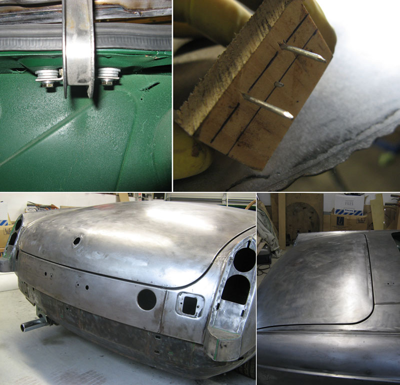
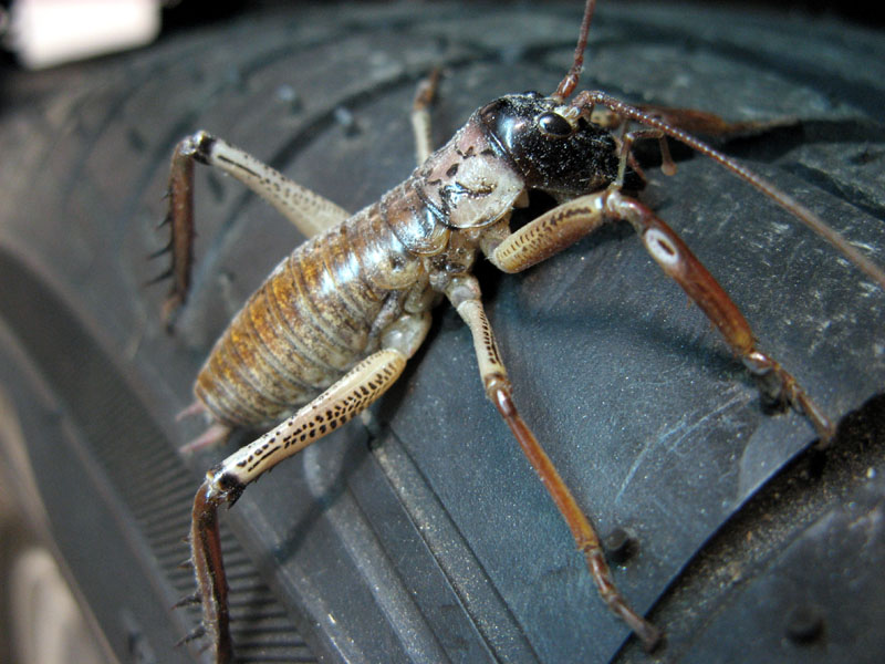
This is one of the unseen hazzards of restoring old MGs. Debugging. In this case a Weta! It was up under the
front wing where I couldn't see it. I went to lift the wing off and thought that's odd, feels like a spikey
piece of wire under my hand. Then I realised what it was and jumped! They are harmless of course. They just
have a habit of startling you. He was safe enough (just a little pissed off) and I let him go outside.
The other major job I had to do was replace the suspension. Since mine was a RB car originally it is sitting
far too high. The rear springs I have had previously de-arched so they now allow the car to sit at the right
height. The rear shocks were replaced with Spax telescopics. A lot of people do this mod and then find the
rear of the car is far too stiff. It is true they are stiffer than the original lever arms. On my car though
I have also greatly stiffened up the front end. Suspension mods need to be done in balance. If you change the
front you need to change the rear to keep the balance the same. I think people who simply replace the rear
lever arms with telescopics will have problems as now the rear is too stiff for the front.
The front suspension on MGs is different on chrome bumper and rubber bumper cars because of the front
crossmember. On the later RB cars to increase the ride height as mandated by the stupid Yanks they basically
changed the crossmember so it sits one inch or so further away from the body. This required a change to the
steering rack and column as now the front geometery was all different. This is why you also can't just put
a CB crossmember on a RB car without changes to the rack or the rack mounting and the steering column.
On the front of my car I lowered it using shorter, stiffer competition springs in the RB crossmember.
This of course shifts the rest position of the A arms so to compensate you need to use lowered front bump
stops so you have enough suspension travel. I also fitted uprated valves to the front shocks to account for
the stiffer springs. Finally I added an uprated front anti-roll bar (the rear one is removed). The front end
sits much lower and is much stiffer now. It looks and should handle better!
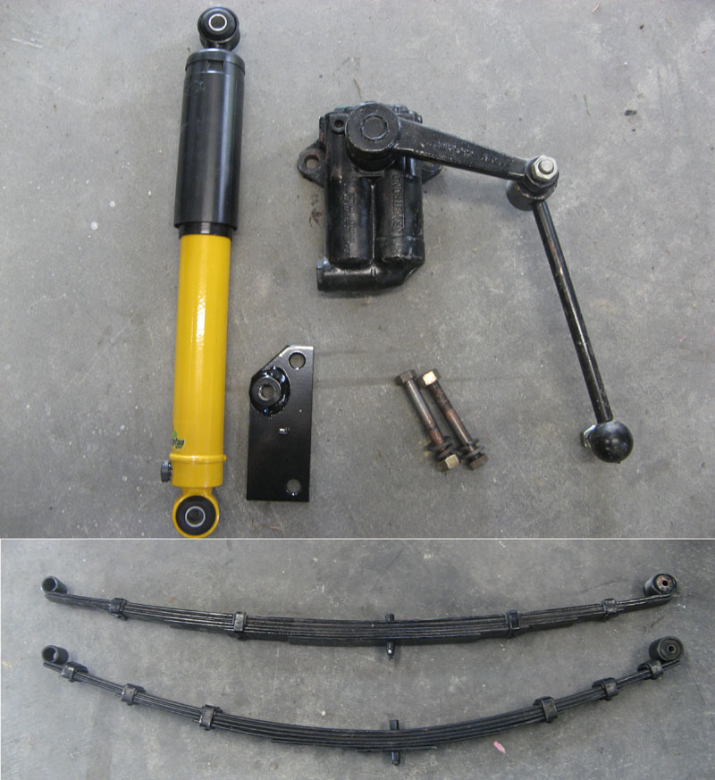
The picture above shows the new rear shocks. The new telescopics on the left and the old lever arm on the right.
You can also see my original rearched springs and under them the new, 'lowered' springs. It turns out my
old springs were correct and the new springs were still too high even though they are lowered ones! Replacing
the lever arms involves removing them and then replacing them with the top bracket in the picture. You use
the original lower mount but you basically turn it around so it is up the other way to normal. The shocks then
mount between the two. Since the rear springs are lowered I also need to reduce the rear bump stops height. You
do this by removing about an inch from them to make sure you still have enough suspension travel. The shocks
are adjustable so you can set the stiffness of them manually.
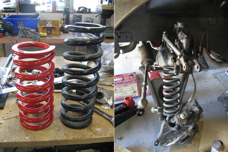
This shows the new front springs. You can plainly see how shortened they are. To make up for being shorter they are
also stiffer then the originals. Don't ask me why they are bright red! You can see how I replace them. You remove
upper trunnion bolt of the suspension from the lever arm and also remove the steering tie rod as well. You do all
this with a trolley jack under the spring pan supporting it. The jack holds the tension on the spring. You need
the car up high on stands to have enough space under the pan to fit the jack when raised up. You then slowly lower
the jack letting the lower spring pan drop. Doing this releases the spring tension in a controllers way. By the
time the jack is down the tension should be released and you can push the spring pan down and remove the spring.
YOu do have to be careful that the stub axle doesn't drop forwards suddenly since obviously the top is normally
held in place with the trunnion bolt and steering tie rod. Also make sure you don't stress the brake hose!
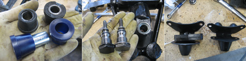
I replaced the rubber bushes all around with new polyurethane Superflex blue ones. This are supposed to be a lot better
than the originals. I also uprated the front shock vlaves to make them stiffer. This is a simple matter of swapping
the old valves for new ones (one of the smaller valve springs is not shown here). Finally because the lowered
springs mean less suspension travel you need to fit shorter bump stops. The originals comes with an alloy spacer. The
lowered version are just the originals with this removed and the stop shortened. If I had known I could have
modified my existing ones I think instead of buying new but they aren't too expensive.
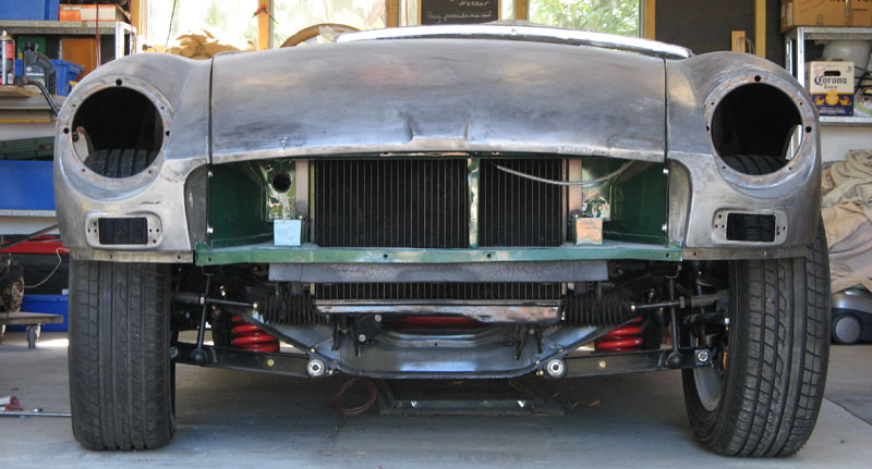
Her is the car after the front suspension mods. I also replaced the usualy front anti roll bar with an uprated (i.e.
fatter) one. The rear anti roll bar present on these later cars was removed some time ago. The angle of the
picture makes the suspension look a little crooked here. You can see though how the lowered springs mean the A
arms are higher on the outboard side than the inboard and that the steering rods are also angled. This can
cause problems with bump steer apparently (where the suspension going up and down causes the steering to move
making the car 'twitchy') but hopefully since the angle is slight this won't be too much of a problem. After
taking this photo I also aligned the wheels so they look a lot less knock-kneed then here now!
Page 1 - Page 2 - Page 3 - Page 4 - Page 5 - Page 6 - Page 7 - Page 8 - Page 9 - Page 10
Page 11 - Page 12 - Page 13 - Page 14 - Page 15 - Page 16 - Page 17 - Page 18 - Page 19
Page 20 - Page 21 - Page 22 - Page 23 - Page 24 - Page 25