Page 15
Page 1 - Page 2 - Page 3 - Page 4 - Page 5 - Page 6 - Page 7 - Page 8 - Page 9 - Page 10
Page 11 - Page 12 - Page 13 - Page 14 - Page 15 - Page 16 - Page 17 - Page 18 - Page 19
Page 20 - Page 21 - Page 22 - Page 23 - Page 24 - Page 25
March 2009
All my updates are getting a bit out of order here since I have done a lot in the last few months but
I will try to cover everything even if not in the order I did them!
About the same time I collected the seats I also collected my new windscreen. I had stripped and
cleaned the old one using Easy Off oven cleaner to remove the old anodising. I then sanded it all
back with wet and dry paper. There are still a few small blemishes on the frames but they weren't too
bad. You can have them reanodised but I have heard that with old aluminium you sometimes don't get a
good finish. I decided to send mine away to have them powder coated and the screen assembled. This is
one of the really horrible MGB jobs and it is easy to end up cracking screens. I choose a reasonably
dark grey tinted screen. The screen was assembled and I collected it. I also got some a sun visor kit to
fit as well. It was then that things went wrong. Fitting the kit requires you to rivet the mounting
points to the screen frame. Mine had holes for these so I put them in place very carefully to avoid
cracking the screen. That all went fine until I realised I had the mounting brackets on upside down!
So, very carefully, I had to drill out the old rivets, flip the mounting brackets and then re-rivet them
in place. Obviously being very careful the whle time. The problem came when I drilled out the old rivets.
I was very careful not to let the drill poke into the glass. But when you drill out rivets you get left
with the end of the old one inside the frame. When I pushed in the new rivet it must have pressed on this
left over piece which then pressed on the screen which then cracked right across one corner!
Needless to say I was not impressed! After I stopped swearing I had to pull the screen apart again. I
ordered new glass and while I waited for that to arrive I fitted the bottom seal to the screen as this
hadn't been done on the first screen. You can fit this seal, which has a T shape that slides in a slot in
the bottom rail, before or after assembling the screen but I think it is easier doing it first. This can
be a bastard of a job and mine was made harder since the frame has this extra coating of powder coat on it.
The trick is to use lots of lubrication. I use Lanolin spray as it is slippery and is a good corrosion
inhibitor and it won't harm the rubber.
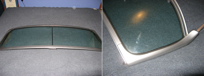
Assembling the screen is a major job. You need a lot of tension on the side frames to pull them in to the
right position. I used ratchet straps to carefully pull them in. You need to be careful since as the screen
is curved too much tension and it could snap right in the middle! The trick is tension, a big rubber mallet
to go slowly a little at a time. When screwing the top bracket on you need to make certain you get the
screws that hold the top on in the proper places. There are long and short screws. Get it wrong and the screw
will crack the glass and you get to start over again.
I finally got it all back together and now the screen is sitting on the car but isn't attached. I am letting
the weight of it slowly flatted the bottom seal which has a tendency to curl under meaning the screen is
difficult to push right down onto the car. The other thing to be careful of is when you bolt the screen to the
car body. You MUST have the correct shims there to take up any slack. If you don't you will pull the bottom
legs of the screen frame together and you will crack the glass. Maybe not right away but one day as the car
body twists in real use.
One final thing Neville did when he assembled the screen is paint the insides of the frame satin black as well
as the central spoke. This makes the screen blend in to the surroundings more rather than standing out.
I have also been busy doing some more body work. The poor car is so bashed about it will be hard to make her straight
but I am trying the best I can. One place she needed work was the front right wings rear edge which was
dented in so it was about 5mm or so lower than the front edge of the door. I fixed this with brute force and
a big screwdriver! A piece of wood between the A pillar and a large flat screwdriver allowed me to carefully
prise the wing into the right position. It is still a mm or so depressed but that can be filled.
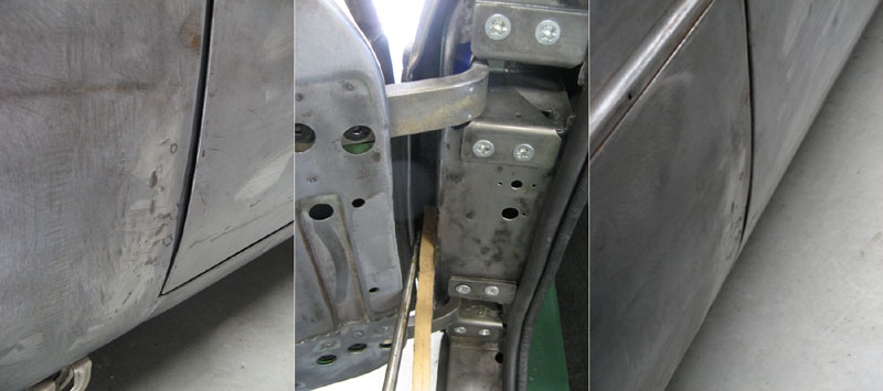
One major problem is the right rear quarter which has been in a large bender in the past. The whole rear quarter
is quite out of shape and this was obvious when sighting along the side of the car. The problem is that
above the wheel the body has been pushed out somewhat. I decided to carefully try to push it back in. My
method was somewhat odd. Basically I used a 2x4 from the roof down to the body to hold the car in place
vertically and another 2x4 and a jack between the side of the car and the wall of my garage. By carefully
extending the jack I was able to push the side of the car back into place. It's not perfect and the car
will always have a kink along the side but it isn't so bad now. Oddly it is only visible if you sight
right along the side of the car from the front. If you look from the rear you don't see it. Of course paint
might make everything worse but I have a plan. In following with my semi race car theme I might paint the
white number circles on the doors (without race numbers) as a trick to break up the side of the car and
draw the eye away from all the faults! Also I need to remember I am a perfectionist but most people aren't.
If I don't go around pointing out the flaws to people (which I tend to do) most of them will never notice!
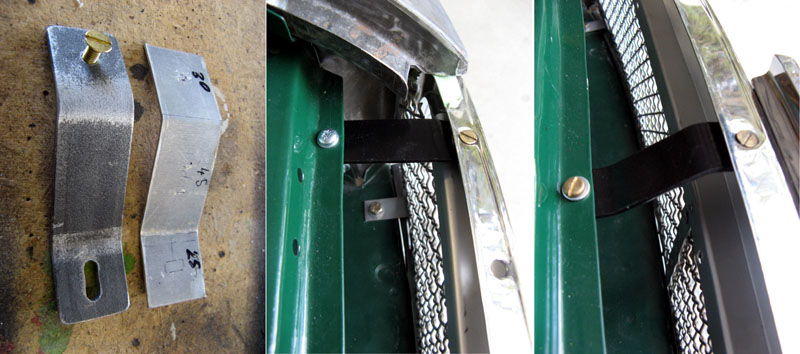
Another custom job was mounting the front grille. There is a mounting kit available that has three brackets
that go from the top of the grill frame to the slam panel. I found though that these didn't put the grille
far enough forward. I want mine flush with the wings and the Sebring front valence. So I made my own
brackets! I made simple ones first from thin aluminium. This is easy to hand bend into the correct shape.
Once those were done I copied the brackets using 3mm steel. Oddly on my car the right wing is about 1/4
of an inch further forward than the left wing but the left grille mounting bracket needed to be 1/4 of
an inch longer than the right. Buggered if I can figure out why though. Something is out of shape
somewhere but the truth is these cars are just like that. You can see it in how all the panels have huge
mounting holes so you can shift things around to get them to fit!
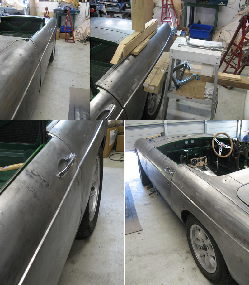
With the grille sorted out I started working on mounting the front fibreglass Sebring valence. Normally an
MGB has a steel valence that sits under the bumper. This valence is not flush with the front of the car but
instead it sits about an inch back. You can debumper a car and leave the valence where it is for a more
racing kind of look (and a lot of race cars do just this) but the 'proper' way of doing it is to fit the
Sebring valence flush with the front of the car. To do this you need to space it out. To fill the space
under the grille I made a spacer from square steel tube. The was just the right size to get the valance
flush. It did need to be curved to follow the line under the grille. I made a cardboard template then
simply bent the square tube in the vice by hand to the right curvature. I then drilled holes through it
to allow me to bolt it to the old valence mounting points which are captive nuts on the body. The screws
are inside the square tube so not visible when it is mounted. I drilled and tapped further holes in the
spacer that are used to bolt the fibreglass to.
Under the wings I use the old valence mounting points to mount the fibreglass valence. To space it out I simply
used a stack of metal washers. For the mounting point closest to the grill though I needed to machine up
custom spacers from steel. These are bolted to the car from behind though the original mounting point and they
are tapped so the valence can be screwed on from the front. I will have to Loctite the screws (which will
be Allen button head screws so they don't shake loose.
Now, getting the front valence to fit isn't an easy job. These things will not just bolt on! Well, they
will but they'll look crap! This is how mine looked when first fitted with the spacer.
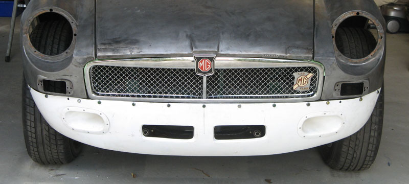
It doesn't look too bad until you look more closely. The biggest problem is that the curvature doesn't nicely
follow the body. You can see under the side lights how the valence doesn't curve. This is because of the
rigid brake cooling ducts fitted to the fairing. These make the valence far too stiff to bend at this point.
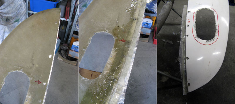
To get around this I probably went further than any sensible person should go. First I removed the ducts by
cutting them out. This allows the valence to bend nicely to follow the body. Next I needed to build up the
edge of the valence so that the gap between it and the car is more even. I need to build it up about 1/4 of
an inch around the outer edges. Luckily the valences are made on the cheap with polyester resin. This is
since you can simply add more fibreglass over the top of it and it will bond to it easily. The valence isn't
at all structural of course but purely cosmetic. To build up the edge I first ran a strip of aluminium tape
along the edge of the valence up to the point I wanted the valence to go to. I then put another layer of tape
over that one but overlapping it. Then I added several layers of fibreglass cloth and resin from inside the
valence. When this is dry you can peel off the tape and you end up with a defined line showing where the
edge should be. I use a random orbit sander to sand back down to this line. I usually paint on another few
coats of resin just to seal the edges.
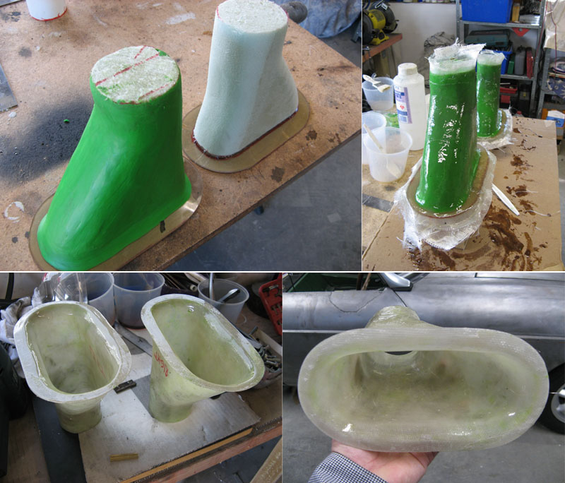
Once the valence was nicely fitted to the curve of the car I came back to the ducts. The original ones are far to
flat to fit the curvature of the valence properly so I couldn't use them. Instead I decided to make my own new
ones. I started with some thin acrylic. I heated this up with a hot air gun then carefully curved it by hand
to fit the curvature of the valence. Then I made up some foam blocks to be the correct shape for the inside of
the ducts. These I hot glued to my acrylic which I had cut to form the flat face of the ducts. I would use this
as a mold to form my new ducts. First I needed to coat the foam which is dissolved by the resin. I covered the
entire foam surface with plasticine then smoothed it down. Over the top of this I layed up my fibreglass and
resin. Since I was only making one set of ducts I wasn't worried about destroying the molds when was finished.
Once everything was set the mold was pulled out and the edges of the duct trimmed. The inside will need a little
finishing to make it all smooth but this can be done with filler or resin and Q cells (small glass beads you mix
with the resin to bulk it up then you can sand it smooth).
It is worth noting all of this took weeks to do! Lots of adding fibreglass then waiting for it to cure then sanding
it smooth. I still need to give the thing a final going over with filler and a final sanding. I will post a
picture when it is all done.
Page 1 - Page 2 - Page 3 - Page 4 - Page 5 - Page 6 - Page 7 - Page 8 - Page 9 - Page 10
Page 11 - Page 12 - Page 13 - Page 14 - Page 15 - Page 16 - Page 17 - Page 18 - Page 19
Page 20 - Page 21 - Page 22 - Page 23 - Page 24 - Page 25