
Building a MAME console inside a TARDIS
Introduction
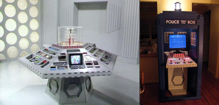
Fig 1. Real console and MAME console
Now that the TARDIS was built I had to start on the MAME console itself. Again I used MDF as the building material and after the complicated TARDIS build making the MAME console was relatively easy. The console itself is shaped to make maximum use of the space inside the TARDIS as well as trying to look like something that would belong inside the TARDIS. I did have to make a lot of compromises there though.
Part Two - The Console
To go back to Part One - The TARDIS click here.
Design
The biggest issue in designing the console was making it so that it would fit inside the TARDIS and still allow the doors to open and close. It also obviously needed room inside it to house the PC and associated bits and pieces. There needed to be space for a control panel and also room for the monitor to sit on top. Due to the low height of the TARDIS doors the control panel needed to extend past the front of the doors. The trick to doing this was to make the control panel itself fold upwards when not in use.
 Fig 2. Another famous folding design
The console is a simple MDF box open at the back and with a removable panel in the front which allows access to the PC inside. The base extends out past the front of the console body to provide stability. When the doors swing inwards the pass over the top of the base easily. The front panel is held on with four magnetic catches. The back of the console can be left open as it isn't seen once the console is in place inside the TARDIS. This allows for better cooling of the PC and power supply that live inside the base and also allows access to the back and side walls of the TARDIS.
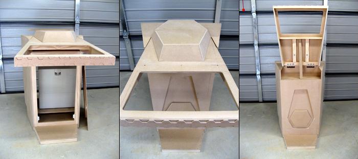
Fig 3. Console design
The folding panel
The trickiest part of the console is the folding control panel. This needs to be easy to detach to allow the console to be moved around and put inside the TARDIS. It has to fold easily and it has to be strong and secure. When you're on wave 5 of Defender and you've just used the last of your smart bombs and you're surrounded by mutants and desperately trying to hit the hyperspace button the last thing you want is a floppy control panel! To make the panel very rigid and to set it far enough back to swing out of the way of the doors the top of the console uses a stepped design. The hinge line is set on top of the panel and this is set back from the front edge of the console. The amount it is set back is about the same as the height of the back of the panel so when it is folded up the bottom edge of it is almost flush with the front of the console. When folded down the bottom and back edges of the panel fit hard up against the step in the console. This takes all the weight of the hinges and makes the panel very secure. You don't need anything other than weight to hold it down and when you're using it you are of course pressing down on the buttons and sticks holding it firmly in place.
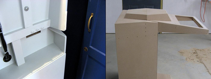
Fig 4. Folding panel
The hinge line and monitor plinth
The hinge line is where the hinges are attached and the point about which the control panel rotates when folded. To provide a nice strong point to attach the hinges I used wooden battens attached to the MDF to give me a great thickness to bolt the hinges to. I used loose pin hinges as I did on the TARDIS doors so it is possible to pull the pins and completely separate the panel from the console.
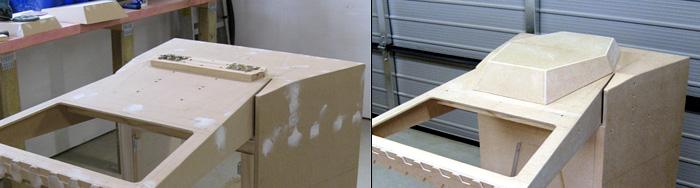
Fig 5. The hinge line and monitor plinth
The monitor plinth is what the LCD screen sits on and this is made in two parts. The first part is attached to the folding panel and moves up and down with it. The back edge of this sits right above the hinge point and it neatly hides the hinges. This part is held on by two long bolts from underneath the panel allowing it to be removed to give access to the hinge pins. The rear section is not attached at all and is free to move backwards and forwards. When the panel is folded up the monitor sits on this part and it is pushed to the back of the console to allow clearance for the panel to fold. When the panel is folded down this piece is slid forwards over the hinges to hide them and make the plinth whole. The monitor is then shifted onto the front part of the plinth.
Keeping it up
 Fig 6. I knew one day those spam emails would be useful for something
A problem they say we all have at one time or another. At first I was thinking about all kinds of complicated methods to keep the control panel in the upright position. Magnetic catches, gas struts, cables, etc. All of these were way too complicated and actually completely unnecessary. The solution was 6 inches of nice, hard wood. When I was building the console I would hold the panel up out of the way with a piece of wooden batten. Why not use the same method on the finished console? A short piece of wood neatly fits between the rear edge of the panel and the bottom of the step on the console. The ends are covered in felt to avoid scratching the paint. When the panel is to be folded down the block is removed and can sit unseen on the step under the panel. The block can be seen in the figure (Fig. 4) above next to where the cabling enters the console base.
Painting
The console was painted in exactly the same way as the TARDIS. First a good sealer/primer followed by three coats of a good, hard wearing enamel paint.
The button panel
The more observant amongst you may have noticed the gaping hole in the middle of the folding panel. This is there because the actual buttons and controls are mounted to a separate piece that is bolted in place. This is done for several reasons. It allows me to use something other than wood for the panel itself (in my case I used 6mm thick white acrylic), it allows me to change the panel easily at a future date and it means you can wire the panel as a separate unit. Before even buying the acrylic I mocked up the control panel using cardboard.

Fig 7. Panel mockup
The cardboard panel actually proved to be strong enough to be useable (as long as one wasn't too enthusiastic at the controls ). Considerable time was wasted, errr I mean well spent, actually playing games on the cardboard panel with some temporary wiring. The button layout I choose is reasonably generic to allow me to play most games. The stick on the left is a simple 4/8 way J-Stick from Ultimarc. The open nature of the bottom of my control panel means it is easy to reach underneath to turn the restrictor plate in the stick from 4 to 8 way.
A lot of people wonder why you can't just use the stick in 8 way position all of the time. The answer is some of the older games such as Pacman only support four direction movement - up, down, left and right. When a game supports 8 way movement what it is actually doing is reading the diagonals as two directions at once. So upper left is seen as both up and left at the same time, lower right is the same as both down and right, etc. A game supporting only four way movement can be 'confused' when seeing diagonals as it is only expecting one direction at a time.
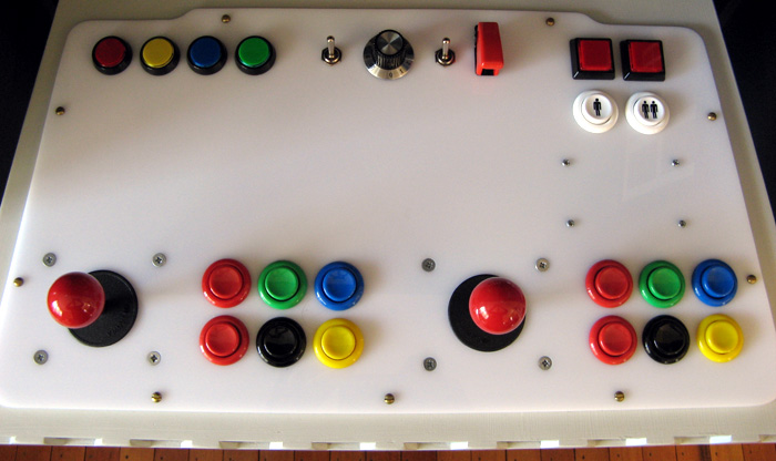
Fig 8. Controls
The stick on the right is a fancy-pants Ultimarc 360. This is an analogue joystick that connects to a USB port. It is also totally mappable and can be programmed to behave as a digital stick, an analogue stick or even a combination of the two. Different mappings can be downloaded to the stick for each game. The four buttons on the top left are illuminated MAME control buttons. They map to ESC, TAB, P (pause) and Enter. Next to them are the switches/volume control for the audio system and panel lights. The switch under the missile cover is wired into the PC power button. You can turn the PC on and off from this one switch. Next to that on the far right are the coin and player buttons. All the fire buttons are proper arcade quality micro switches. I would like to add a trackball controller in the spare space although this is a very expensive control.
A newt
This is a picture of my pet newt Fungus (named after Fungus the Bogeyman). Aaaahhhhh, isn't he cute.
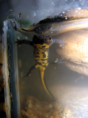 Fig 8. Fungus the newt
He is here to get back at all those people who spoil perfectly good web pages by including totally superfluous of their cats. I don't care about your cat. No one else cares about your cat. Damn cat owners and their Toxoplasmosis addled brains!
Control panel wiring
The first step in wiring up the control panel is to drill the holes to mount all the controls. The acrylic is easy to drill but you have to watch you don't chip the edges of the holes. I bought a suitably sized spade bit to drill the holes for the buttons to mount through. To avoid cracking the edges I would clamp the panel in the vice with a piece of MDF backing it. You can then drill through the acrylic, first a pilot hole then with the spade bit, and into the wood and avoid splintering the back edge of the hole. After drilling the holes it is a good idea to run a half round file around the edges of the holes to make sure there are no sharp edges left. DO NOT run your fingers around the inside of the holes until you have done this to avoid getting blood over everything when you cut yourself.
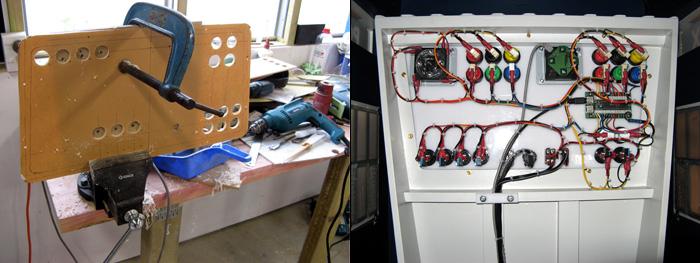
Fig 9. Drilling and wiring
The wiring is all done with crimped spade connectors to hook up to the terminals on the push button switches and 4/8 way stick. From there they go into the Ultimarc iPac controller on the right hand side. The iPac and 360 stick have USB cables that run to the PC. There are additional wires for the audio controls and other switches.
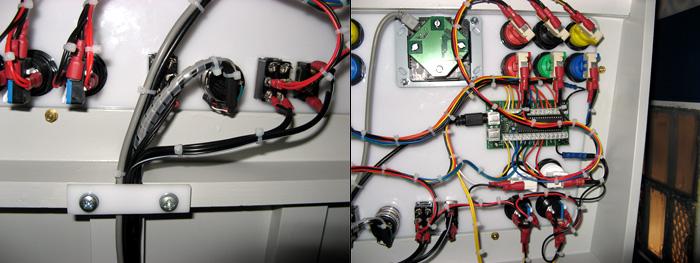
Fig 10. Wiring detail
All the wires are carefully cable tied together and held firmly in position by the clamp made from a piece of off cut white acrylic. This takes all the strain off the cables which is necessary as the panel has to move though 90 degrees from the upright to the playing position. On the right the iPac is visible. This controller is what converts the button presses into the keyboard commands MAME expects. The iPac is fully re-programmable and also has some nice features such as a shift key option to allow you to assign more than one function to particular buttons. All of the wiring that passes into the base of the console can be unplugged inside the base of the console so the control panel can be completely removed when necessary.
Wiring inside the console
Inside the base of the console there are a number of different things. The main thing is of course the PC. The iPac connects to the USB port but has a keyboard pass-through on it so you can still attach a standard keyboard as well. I leave this out of sight in the base of the console unless I need it. There is actually a little shelf inside the base of the console that the computer is sitting on. Under this base I have a 12 volt 5A power supply. This supplies power for the flashing light on top of the TARDIS, the internal light, the illuminated buttons on the control panel and the power for the amplifier driving the speakers. There is a second power supply to supply the mass driver amplifier which I shall explain shortly.
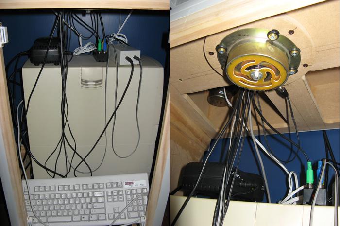
Fig 11. Inside wiring
On top of the PC, from left to right, are the mass driver amplifier, the power distribution box and the audio amplifier. The audio amplifier has leads running from the PC audio out, leads running to the two speakers in the rear of the console and also wires running up to the control panel where they attach to a volume control which is also the power switch. The small black box with the RCA connectors is the power distribution box. RCA plugs and sockets are usually used for audio signals but I used them as power connectors here as the power requirements are very low and I can use different coloured connectors for each different system. The mass driver amplifier powers the driver itself. That is the round metal lump seen in the right hand image. A mass driver is like a speaker or sub woofer without a paper cone. It is bolted firmly to the console and the amplifier feeds it with only very low frequency sound. These low frequencies are then transmitted to the whole console. This provides a nice low bass response without the need for a big sub woofer box. The power to the mass driver is controlled by it's own toggle switch on the panel. Just visible up behind the mass driver is one of the two standard speakers. These are attached to the top of the console and are covered on the outside with circular white covers. Also inside the base under the PC shelf is a 6 way power board with a surge protector built in. One mains lead feeds this power board and the PC, monitor and all the power supplies are plugged into it.
Assembly inside the TARDIS
Assembling the console inside the TARDIS is relatively easy but there is a trick to it. The console base is too wide to fit through the TARDIS doors, even if the doors are removed. This was done to absolutely maximise the space inside the console to be able to fit in the PC. The trick is you put the console base in through the side of the TARDIS. Once the TARDIS is assembled one side wall can be completely removed. The console, with the control panel detached, is then lifted in through the side opening. Once in place the wall can be reattached in position. Since the back of the console is open you can easily get in to reach the screws holding the wall panel in place. Before doing any of this it is very, very important to make sure the mains power lead that runs the whole thing is in place under the base of the TARDIS. When assembled there is only about 10mm gap between the base of the TARDIS and the floor. Enough to pass over a cable. Not enough to get a cable with a plug on the end underneath it! Yes, I figured that out by experience.
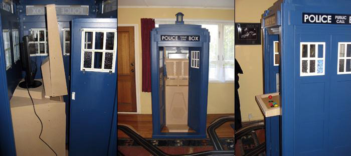
Fig 12. Installing in the TARDIS
With the wall back in place you can then put the PC and associated bits inside the console base. I then attach the control panel and put the hinge pins in place. Next the front part of the monitor plinth is screwed into position from underneath the panel. I then thread each of the wires from the panel through the hole into the middle of the console. I start with the largest connectors, the USB plugs, and finish with the smaller ones as the space around the hole gets filled with cables. Once all of these are connected up you can put the rear part of the monitor plinth in place and sit the monitor on top and connect it up. The monitor I am using by the way is a 19 inch LCD. Finally when everything is connected up and in place you simply pop the front panel in place where it is held by it's magnetic catches.
Complete!
And that is basically it. A MAME console in a TARDIS!
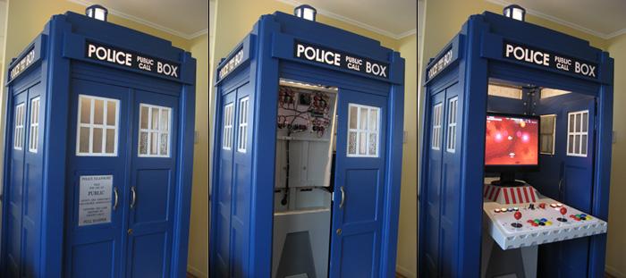
Fig 13. The complete TARDIS MAME console
Adding a Trackball - July 2007
I was able to buy a X-Arcade trackball kit on the local auction site for a very good price. I always planned on having on, mainly to be used for controlling Windows rather than for games as it aslo functions as a normal mouse. I had left space on the original control panel for a Trackball but I underestimated the size of the thing! The ball itself is 3 inches diameter meaning the housing for it is massive. I had to make a new panel! Making the new panel didn't take too long. I shifted the PC power, volume control and sound and light switches to a smaller aluminium panel I mounted on the front sloping face of the monitor plinth. They are actually easier to use here. I also upgraded the PC inside the cabinet to a much faster machine.
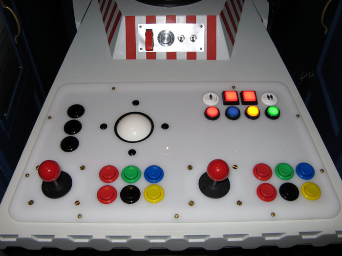
Figure 14. Trackball in the new panel.
The trackball works great and it is very solidly build yet can be taken apart for cleaning. The three black buttons on the left are the left, middle and right mouse buttons. Having the ball up above the player one buttons gives you lots of space to get to it without the sticks getting in the way.
To go back to Part One - The TARDIS click here.