
Building a MAME console inside a TARDIS
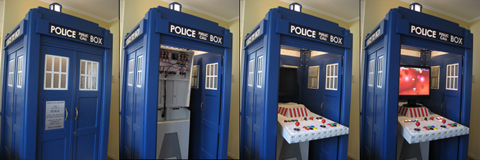
Fig 1. Console unfolding
Introduction
How to put a MAME console inside a TARDIS? Yes, that's a question all right. Should be easy right, what with the TARDIS being bigger on the inside than the outside. Grrrrr! If I were to wring the neck of everyone who mentions that (and believe me after hearing it for the umpteenth time you do feel that way inclined) we'd have a body count approaching that of your average Charles Bronson film (by the way Charles Bronson would kick Chuck Norris' arse).
 Fig 2. Mr. Charles Bronson
It turns out it isn't so easy. And if you follow this through (it is a long and rambling I'm afraid) you'll see why. The story is in two parts since the TARDIS and the MAME Console were constructed as two separate projects and combined at the end. I made the TARDIS first then designed the Console to fit inside it. First though I should probably explain why this all came about.
Part One - The TARDIS
To go on to Part Two - The Console click here.
It all started with Linux
Linux, what the hell is that all about? It all started with a spare computer I had. A freebie from my days working at Intel where they decided it would be a good idea to give all their employees a free computer. Who was I to complain? After it had long been relegated to the role of spare PC I decided to install Linux on it. Mainly because I had just bought a new Linux based Nokia hand held and also on the insistence of a friend because he, as most Linux geeks do, told me I should be running Linux instead of Windows. I think it's because Linux geeks are computer masochists and they want us all to suffer. All that ls -al and rm -rf * bollocks. Who knows what's that's about?
 Fig 3. Linux geek
Anyway, Linux didn't last long (not after that last command anyway it wouldn't) and I soon had Win2k back on the box. I needed something useful for it to do however and it was then I discovered MAME.
M.A.M.E Multiple Arcade Machine Emulator
For those of you who don't know what MAME is I shall explain. MAME is a piece of software you run on a PC that lets you run and play thousands of old arcade games. It works by emulating the hardware necessary to run the original game ROM files. So the games aren't a simulation of the originals. They ARE the originals. The aim of the MAME development team is to ensure the old games aren't lost as the hardware becomes more rare. Note that their purpose is to preserve these items of electronic history as exactly as possible. They aren't trying to make every game playable on your regular home PC. The fact that most games are playable is just a nice side effect for people who love the classics. This is explained on the MAME homepage in the FAQ.
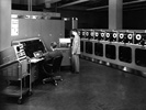 Fig 4. MAME early adaptors
To run MAME you don't need the latest, fastest machine possible (although a better spec machine will work better with some games). I am using a HP Vectra VL400 1GHz Pentium with 512MB of RAM and an ATI Radeon 9550 video card. Hardly the best games machine around. This quite happily plays a lot of the games and certainly the ones I like to play. The biggest problem however isn't the PC hardware itself, it's the controls. You can play MAME with a standard keyboard, joystick or mouse but to be honest it really just isn't right. Anyone who is serious about MAME will soon realise to experience all those old games properly you need the proper controls. This is where building your own arcade cabinet comes into it.
Building your own arcade machine
What is an arcade machine? I remember when I was a kid we always referred to them as 'spacies' machines. Basically it's a big wooden box containing the game hardware and a nice big screen, speakers and a control panel. Usually they are tall upright things you stand at to play the games. Some were what are known as cocktail cabinets where the machine looked more like a coffee table and you sat down, typically one person each side, and played the game with the screen flat before you under a glass top. Others were shaped like mini cockpits you sat inside to play the games. One thing they all had in common was a slot to throw your money into.
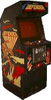 Fig 5. Defender circa 1980
A MAME cabinet is basically a box of one of the types described above built by someone specifically to house a PC and screen and controls and generally made to look a lot like one of the original games machines of the past. If you're building it yourself you can of course leave off the coin slot. Well, unless you're a cheap bastard and you like charging your friends for games. Charge the Linux geeks double - they deserve it!
Control panels
In the original games the control panel depends of course on the type of game. Some may have had only a joystick (like Pacman) whereas others had a joystick and buttons all over the place (like Defender). Others may have had trackballs (like Centipede) or steering wheels (like Pole Position). Most would have extra buttons for selecting the number of players or other special functions. The point is different games had different control panels. With MAME you want a control panel that is flexible enough to play all the different types of games you are interested in. If you only play Pacman you only need a simple panel. If you want to play many different games you need to come up with good generic control layout with enough controls to allow you to play each different game.
 Fig 6. Advanced MAME control design
How MAME supports controls
MAME basically treats key presses from the standard PC keyboard as digital inputs (like buttons or digital joysticks) on a real arcade machine. For example the arrow keys map to left, right, up and down joystick movements and pressing CTRL and ALT is like hitting the fire buttons. MAME also supports things like PC mice and trackballs as well as analogue joysticks. The good thing about MAME is all the controls are configurable. It also provides keys for things like the player select buttons and to simulate people inserting coins into the machine.
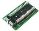 Fig 7. iPac controller
A MAME control panel will usually have a bunch of buttons and joysticks and other controls that are wired up to simulate pressing keyboard keys. There are several ways of doing this. You can modify an existing keyboard and wire the buttons into that. This is commonly known as a 'keyboard hack'. There are limitations to this method however and, as Dirty Harry says, "A man's got to know his limitations". A much better method is to use a keyboard encoder (such as the iPac made by Ultimarc). This is a piece of hardware you plug into a keyboard or USB port. It has on it a variety of inputs that you can then wire buttons to. Pressing a button causes the controller to send the appropriate key press signal to the PC. These controls are usually very powerful and flexible allowing you to reprogram what buttons simulate which keyboard keys as well as allowing you to program in special feature like shift keys and even macros to simulate pressing combinations of keys in specific orders.
Making a cabinet
As mentioned before the cabinet is usually a big wooden thing you stand at to play the games. The control panel bolts onto the front and the computer lives inside. People use a variety of different screens. The best is a real arcade monitor. Interfacing one to a PC can be tricky although special video cards are made for just this purpose. An ordinary PC monitor will work too. Some people go to a lot of trouble making their cabinets and the results can be amazing. There are some very clever designs out there for revolving or modular control panels allowing the cabinet to be configured for almost any game. After I had been playing with MAME for a while and, inspired by the other cabinets people had made that I had seen on the Internet, I started thinking about making my own cabinet.
My cabinet
I had been thinking about building a cabinet for a while and had only got as far as sketching out a few designs and looking for examples of other designs on the web. It was about this time I was out with a girl I knew having a drink in a little bar in town. I was staring out the window and thinking about how I could make my own cabinet. I am not a woodworker by any means, my skill tends to be more with metal, but I figured making a cabinet wouldn't be too difficult. As I was thinking this I suddenly realised what it was I was looking at out of the window. Across the road was a HUGE billboard advertising the new season of Doctor Who. On it was a giant TARDIS.
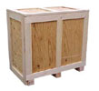 Fig 8. A big wooden box
The idea dawned on me if I was going to be building a huge wooden box to sit in my living room to put this MAME machine in I might as well build an interesting huge wooden box. The idea just made sense (not sure how many drinks I had had by this stage now I think of it) and the idea for the TARDIS MAME console was born.
The TARDIS
Now I should point out here I do like Doctor Who but I wouldn't say I am a mad fan or anything. None of that dressing up and going to conventions or having an answer phone message saying "We are the Daleks! We are the superior beings! Please leave a message after the EXTERMINATE! EXTERMINATE!" or expecting my girlfriend to dress up like Leela the savage girl (although that last idea isn't completely without merit though I must admit) or anything like that. I just appreciate the interesting stories and like the appeal of the decidedly shoddy special effects.
 Fig 9. Fairly typical savage girl
On thing that has been fairly consistent through the 40 odd years the programme has been on is the TARDIS. It is almost instantly recognisable to anyone even remotely familiar with the show. There is something very British about it I find. That quirky, odd sort of sense of humour. To imagine someone came along and said "Lets have this Doctor chappy flying about in a space/time machine, what. And let's make this machine a bright, blue Police Box. And we'll make it so it is bigger on the inside than the outside! Yes, that's a brilliant idea. Right, whose round is it? Another pint Arthur?". Just so British. I am surprised the Americans get it actually considering that after Star Trek and the original Battlestar Galactica (which we all know was just cashing in on Star Wars anyway) the best sci-fi they came up with for a long time was David Hasselhoff driving about in a car so camp it made Chitty Chitty Bang Bang look butch.
 Fig 10. The Hoff and his camp car
Anyway, I digress. The TARDIS, that big, beautiful, blue box with a flashing light on top and making a noise like a constipated photocopy machine, what a brilliant cabinet to put my MAME machine in. Unfortunately there were a few obstacles to solve along the way. First the TARDIS is big. Far to big to fit indoors unless you happen to live on a movie set. Secondly the doors on a TARDIS open inwards. When you're dealing with a rectangular box like this doors opening inwards tend to take up an awful lot of the interior space. Both of these problems were overcome though as you shall see.
 Fig 11. A Dalek
Making the TARDIS
The first thing I had to do was come up with some sort of TARDIS plans. No full plans exist on the Internet so I had to come up with my own. Actually, that's not strictly true. There are people who will SELL you TARDIS plans. Based on pictures of their finished product though I wouldn't bother to buy them. With a bit of research it is easily possible to come up with your own plans. If you do this what you will find out is there isn't actually one definitive TARDIS design.
 Fig 12. Plans drawn up
The actual prop was rebuilt a number of times over the years and there were changes made each time. The same physical props also underwent changes from season to season and even story to story. Certain things such as the colour of the windows and the height of the roof are obvious. There are also more subtle changes such as the size, shape and number of door handles, the colour and design of the door sign and even the wording on the sign. This means you can basically pick and choose the features you want your own TARDIS to have. I went with the earlier style which is considered to be closer to the original Police Box. Now a real Police Box is quite tall, a lot taller than people expect especially with the flashing light on top. In order to have the TARDIS fit inside my house I had to scale it somewhat. I eventually choose a 3/4 scale to build mine. Even then it is still about 1m square on the base and about 2.3m tall.
Materials and tools
I decided to make my TARDIS from MDF (medium density fiberboard). Anyone who has ever watched a home improvement type show will know this as the stuff they make EVERYTHING from instead of real wood. The advantage of it is it is cheap, easy to work with and it comes in various thicknesses. I used sheets of 4.75, 6, 9 and 18mm. My plans were drawn up using these dimensions in mind. MDF can be glued easily but when nailing or screwing it you often need to drill a pilot hole to avoid the material splitting. When painting it you need to start with a good primer/sealer as the material will soak up a lot of paint, especially on the edges.
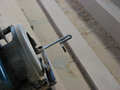 Fig 13. Circular saw
Cutting it was done with a Makita circular saw. I also used an angle grinder, random orbit sander, jigsaw, router and an electric drill. Most of the joints were glued with white glue and also held with small panel pins and screws. I also made use of special furniture fasteners. These are a tapered metal insert screwed flush into a hole in the wood using an Allen key. Through the middle of them is a threaded 6mm hole. These allow you to bolt other pieces to them using a standard machine screw. The TARDIS had to be built in such a way that it can be assembled and disassembled easily to allow it to be moved and so it can fit through doorways.
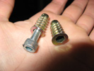 Fig 14. Furniture fasteners
As well as the MDF you need several castors for the base to make it mobile, plain and hammered glass for the windows and plastic for the signs. You also need some form of flashing light for the top.
Construction of the base
The base is basically a flat square with the middle cut out. I made it from two layers of 18mm MDF as the main part of the base. Across the back is a board of MDF to which the castors are attached. I used three castors along the back edge of the base only. At the front are two rubber feet. The TARDIS at rest won't move since the rubber feet hold it in position. However you can shift the whole TARDIS around by tipping it backwards slightly to lift the feet off the ground at which point it can be wheeled around on the castors (a lot like a fridge). Around the bottom edge is a further thin strip of 18mm MDF to hide the bottom of the castors and rubber feet. The middle of the base is hollow since the MAME console that goes inside the TARDIS needs to be sitting directly on the floor to give it stability. In each corner of the base is a hole that acts as a socket for locating the corner posts. The top outer edge of the base is beveled off at 45 degrees.
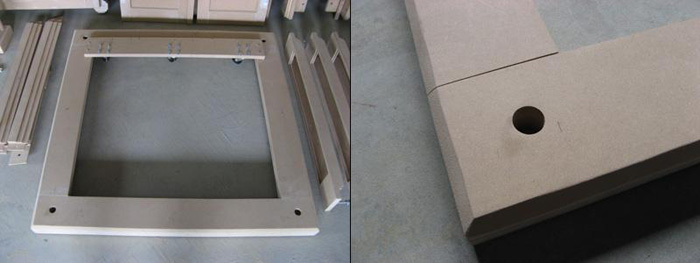
Fig 14. Base and corner detail
The corner posts
The corner posts form the main structure that everything else attaches to. These are made up of several long strips of MDF glued together to make an L shape with stepped corners. In each corner runs a quarter round finishing strip to give the corners the proper rounded look. In the bottom of each post is a wooden dowel (OK, I chopped up a bit of broom stick) which fits into the matching hole in the base. Down the inside of the corner posts are the threaded furniture fasteners. The walls fit up against the inside of the corner posts and bolts pass through them into the fasteners to hold the walls in place. The top of the posts are held in place with a square ring beam of MDF. This ring holds the top of the posts in the correct position and also forms the first step of the TARDIS roof. It is also held in place by long screws into fasteners in the posts.
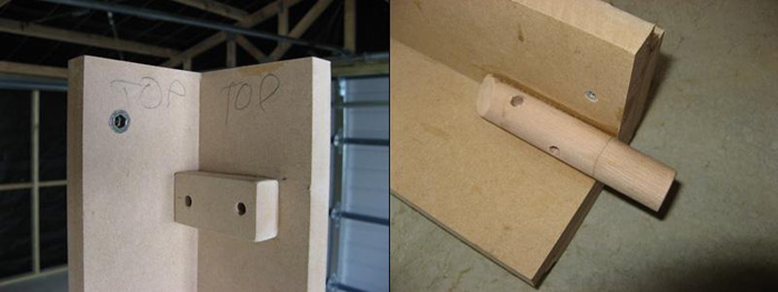
Fig 15. Corner post top and bottom
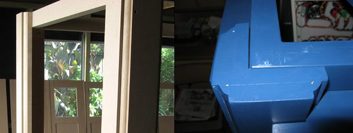
Fig 16. Corner post side and profile
Ring beam
The ring beam is a simple square ring that fits flush with the top of the corner posts. The roof of the TARDIS then sits on top of this beam.
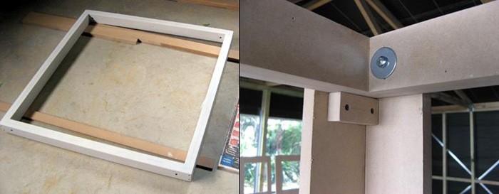
Fig 17. Ring beam and fixing detail
Walls and doors
The three walls and two doors are made from a thin backing sheet of MDF. Onto this are attached the MDF horizontal and vertical strips that form the panels and window openings visible on the outside walls. On each wall there are eight such panels. The top two are the window openings. The bottom six are just recessed panels. I made mine so the panels have beveled edges. To do this I had to cut all the verticals and horizontals with sloped edges then carefully fit them all together. Where the windows sit in place the backing sheet has a hole bigger than the hole made by the recessed panel cut into it. That way the beveled MDF strips form the edges of the window opening. The window frame itself fits into the hole in the backing board and is pressed up hard against the inside of the strips.
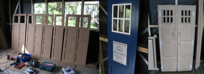
Fig 18. Walls, doors and pull to open panel
Each wall panel fits up against the inside of the corner posts and are held in place with screws through holes in the wall that fit into the fasteners in the posts. The doors are made in the same way as the walls but in two halves. Instead of holes to pass screws through they have hinges along their outside edges. I used loose pin hinges so I can split them easily into two halves. The matching half of the hinge is attached to the inside of the front corner posts. I used three hinges per door. To fit the doors you simply pop them into place, line up the hinges and slide the hinge pin into place. The doors open INWARDS. This is how the real TARDIS props work. To hold the doors closed I used a magnetic catch in the middle of each one. These are attracted to each other when the doors are closed. To hold the doors in place when then are open I use small magnets that attract the top corner of the doors to small screws attached to the walls. On each door is a small brass handle and I also used a small drawer lock to represent the Yale lock that some of the real props used.
On the left hand door the panel under the window is what is called the "Pull to Open" panel. This is a small door that would have originally have had a telephone behind it. On mine this panel doesn't actually open. The panel has a sign on it. The colour, typeface and even wording on this sign changed among the different TARDIS props. I settled for a silver coloured panel with black, laser cut lettering.
Windows
The windows are again made from MDF strips. They consist of a rectangular frame with two verticals and one horizontal across the middle. This forms spaces for six small panes of glass. The bottom two outside panes are a hammered, textured glass. All other panes are clear glass. To make the frame and cross pieces I cut several long boards of MDF. One board was the same size as the width of the window and one the same size as the height. These boards then had strips routed down the length of them to half the depth of the wood. I then used the saw to cut the horizontal and vertical frame pieces across the boards. The slots are arranged so that when the frame is assembled the pieces interlock together by matching the slots up. The whole frame is then one consistent thickness. The frames were glued and stapled together. The window glass was simply glued to the back of the frame using silicon sealant after the frames were sanded, sealed and painted white.
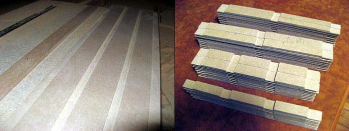
Fig 19. Routing and cutting window frame strips
The windows are held to the back of the walls and doors behind the beveled opening using small canvas clips with felt backing on them. These can be done up tightly enough to hold the windows in place but allow some movement to get them evenly positioned in the walls and doors. Once in position the clips can be done up tightly locking the windows in place.
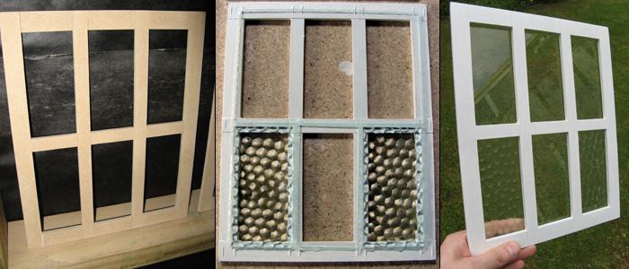
Fig 20. Window frames and glass
The inside of the windows were made opaque by painting over them with a very thin wash of a dirty grey paint I mixed up for various leftovers I found in tins around my shed. The windows still light up from behind nicely but you can't look through them and see inside the TARDIS.
Roof
The roof on my TARDIS has three steps to it. Some TARDIS props (most notable through the Tom Baker years) used a flatter, two step roof design. The first step of my roof is formed by the ring beam at the top of the corner posts. On top of this sits the main roof structure. This is all made in one piece. The base of the roof is again a simple square structure with a flat top. On top of this is the main sloping roof. The roof slopes up to a small square flat section at the very top. On top of this fits the lamp base and flashing lamp.
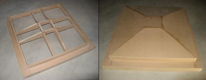
Fig 21. Roof frame and covering
In each corner of the roof is a small capping piece. These caps have the same cross section as the corner posts although they are narrower. I made a length of capping in one piece then sliced it up into the four corner capping pieces. When the roof is in place these line up with the center of the corner posts and make it appear as if the corner posts take a step inwards to meet the roof corners. Nothing but gravity holds the roof in place. It is heavy enough not to move but not so heavy one person can't lift it up onto the top of the TARDIS themselves. Inside the roof is a flat ceiling to which is attached the control panel for the interior light and the lamp flasher.
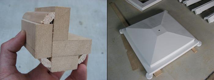
Fig 22. Corner cap profile and caps in place
Flashing lamp
The flashing lamp base is a simple square structure. Onto this are attached four round wooden dowels leading up to a flat, round capping piece. In the center of all this fits the actual glass lamp. Now the original TARDIS design used a Fresnel style lamp but these are rather tricky to get. Even the BBC props department had to resort to all manner of lamp replacements over the years. It is even rumoured they had to improvise and use a Tupperware container at one point! I also had to improvise but I went a little more high tech than Tupperware and used an old gherkin jar. Ok, I went only slightly more high tech. I sandblasted the inside of the jar to make it opaque.
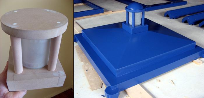
Fig 23. Lamp housing (without dome) and lamp on roof
Inside the jar I used a car trailer light to provide illumination. This is flashed on and off by a small circuit using a 555 timer chip. On top of the round capping piece is a domed top. This is made of a section cut from an old plastic ballcock (I beg your pardon) float. The power cable for the light passed down through a hole in the TARDIS roof to the control panel attached to the ceiling inside.
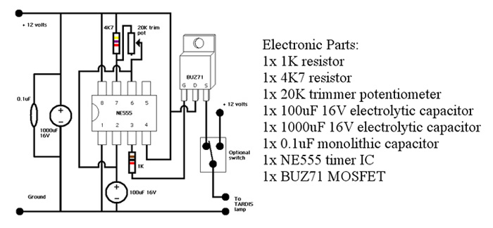
Fig 24. TARDIS lamp flasher circuit
Sign boxes
The signs boxes are made from 6mm MDF. They attach to the outside of the corner posts just down from the top of the ring beam that makes up the first step of the roof. The top and the bottom of each box needs to be contoured to neatly fit against the curved edges of the corner posts. They are held in place by long threaded rods that pass right through the posts and are held on the inside by wing nuts. The front face of each box has a large rectangular cutout. Behind this is a small stepped edge made from strips of MDF.
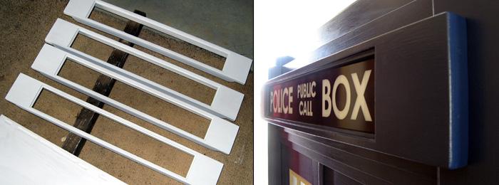
Fig 25. Sign boxes
The actual signs are made from translucent, white acrylic sheet. The letters are formed by cutouts in dark blue, laser cut vinyl that is stuck to the outside of the white acrylic. The white plastic is then held inside the sign box by small wooden blocks that fix it in position.
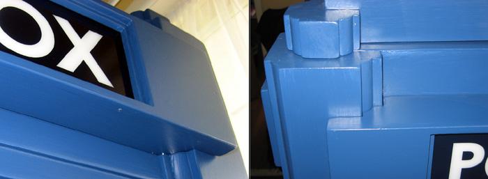
Fig 26. Sign box top and bottom profile
When back lit the vinyl blocks most of the light allowing a slight blue glow where there is vinyl and a white glow where the letters are cut out.
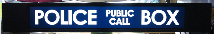
Fig 27. Illuminated 'POLICE BOX' sign
Three steps
The bottom of the sign box sits somewhat above the top of the doors and walls. In the space between these fits what is known as the three step. This is a stepped section that simply bolts to the inside of the corner posts and sits on top of the door and walls. The bottom step sits just above the surface of the doors. The top step sits just below the back of the sign boxes.
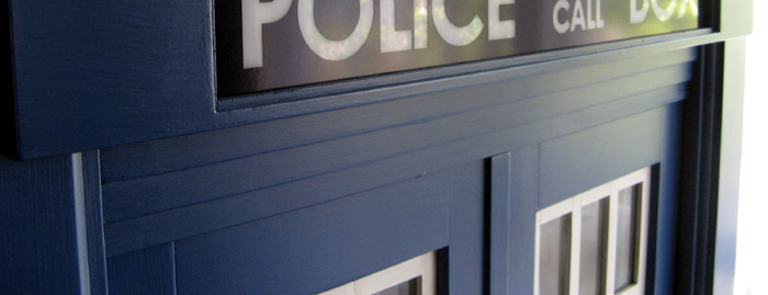
Fig 28. Three step piece between door and sign box
Control panel and internal light
The control panel attached to the ceiling has several functions. It contains the circuit used to make the lamp flash and also houses it's own bulb that works as an internal light for the TARDIS. This bulb is a car stop lamp. As these have two filaments in them I can have a 2 brightness light. The bulb is attached to the bottom of the control panel and hangs low enough down so that it's light can shine through the back of the sign boxes to illuminate them without causing shadows on the back of the signs.
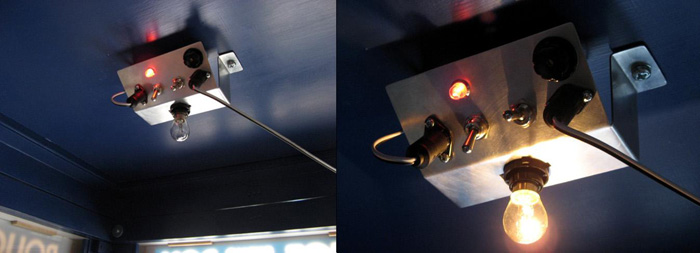
Fig 29. Lighting control panel
The panel has two three position switches. The first controls the flashing lamp allowing it to be off, on permanently or flashing. The second controls the internal light allowing it to be off, dim or bright. Two cables attach to the panel. One heads up through the roof to the flashing lamp. The other heads down to a 12 volt power supply in the base of the console. The cables are attached using 2 pin DIN plugs and sockets (in the old days theses were typically used as speaker cable plugs and sockets). The circuit for the flasher has an adjustment to allow fine tuning of the flashing rate. There is also a fuse on the panel in case anything ever shorts out.
Painting
As mentioned the first step in painting is to seal and prime everything. I used two coats of a good primer, sealer followed by several coats of the blue colour. Painting was one of the slower, more painful jobs of the whole TARDIS build as I had to paint one side of everything, wait for it to dry, turn it over then paint the other side. The final colour I used was a custom blend of blue that started life as 'fish net blue' and ended up 'fish net stocking blue'. It is an oil based enamel so it is very hard wearing and so that the painted panels won't stick together where the pieces touch after they are bolted together. The downside is you need to wait 24 hours for the paint to dry between coats and wait weeks for the paint to achieve full hardness. Painting took well over a week then another week of drying time before I could finally assemble the pieces.
 Fig 30. Painting instruction manual
Assembly
The TARDIS is assembled in the following order. First the base is positioned on the floor. At this point it is very, very important to remember to put it over the power cable that runs the TARDIS and console when it is assembled. If you miss this step you can't then easily get the cable under the base without taking the TARDIS apart. Once the base is in place the four corner posts are stood in position, the dowels in the base of each fitting into the corresponding hole in the base. The corners aren't actually fixed to the base in any way. Weight holds it all together. Even in the great Auckland earthquake of 2007 the TARDIS stood solid as a rock.
Next the roof ring beam is attached. This sits on the blocks screwed to the inside of the corner posts. The blocks mean it sits at the right height. Screws then pass through the ring into the corner to hold it in place.
Next the walls and the three steps are loosely screwed in place. Everything is kept loose until the doors are fitted to allow things to be moved around. The doors are then put into position and the hinge pins put in place. The three step above the doors is also positioned now. The doors are closed and I make sure they sit square and open and close freely before tightening the rest of the walls and three steps into position.
Next the roof is lifted into position on top of the ring beam. On the very top of the roof the lamp is fitted. The lamp base has two small dowel pins that protrude into holes in the roof to hold it into position so it won't slide off. The power cable to it is threaded down through the hole in the roof.
Next the sign boxes are put into position on the outside of the TARDIS. The long threaded rods in the back of the boxes pass through holes in the corner posts and allow the boxes to sit in place while the wing nuts are done up from inside the TARDIS.
Finally the control panel and interior light are screwed into position. The wires are all plugged in and hooked up and the TARDIS is complete!
OK, but where is the MAME console?
For those who made it this far you might have noticed one major emission here. The MAME console. The details of that follow in part two. Before I started making the console I made a small model with cardboard and hot glue to make sure the concept would work.

Fig 31. Highly detailed prototype scale model console
The TARDIS and the MAME console are actually two separate projects that just happen to fit together when complete but either can stand alone quite happily by itself.
August 2007 Update
A small update to this story. Recently Sylvester McCoy (the 7th Doctor) was in New Zealand performing in the Shakespeare play 'King Lear'. He took a day however to appear at a small Doctor Who convention where he spoke about his time as the Doctor and he also posed for pictures and signed autographs. I wouldn't normally go to a sci-fi convention but at the insistence of friends I took the opportunity to take in a part of my TARDIS to have him sign it. Deciding which part was tricky as most of the parts are far too big to carry about easily. In the end I settled for the front sign box since I could easily remove it and since the inside of it is painted white. The inside also remains free from dust and grime!
So now I have a TARDIS signed by an actual Doctor.
Funnily enough he is actually the second Doctor I have met. Back in 1990 I ran into Jon Pertwee in the middle of a bird sanctuary/aviary near Palmerston North of all places. I remember he was very polite and quite happy to talk to us. I didn't ask for an autograph. It didn't seem right to bother a man on holiday. It was just nice to meet him.
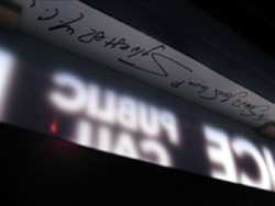
Fig 32. The signed TARDIS
April 2013 Another update
Another update. And one I missed. In Octber 2010 Sylvester McCoy, Paul McGann and Sophie Aldred came to NZ for an Armageddon convention so along I went, sign box in hand, to have it autographed. So Mr McCoy has now signed it twice!
And yesterday I went along to the Lords of Time event which featured Sylvester and Paul again and also Peter Davison, Colin Baker as well as Nicholas Briggs who does the voices of the Daleks and Cybermen in the new Who.
I collected signatures from Peter, Colin and Nicholas. It turns out it was Peter Davison's birthday that day also. Everyone sang to him as he came on stage. Later, at the autograph signing, I gave him my hand made TARDIS cufflinks as a birthday gift (and went home shirt sleves flapping).
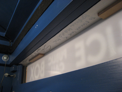
Fig 33. Paul, Sylvester and Sophie.
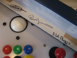
Fig 34. Colin, Peter and Nicholas.
To go on to Part Two - The Console click here.