
A home made jet engine
Page 1 Contents
Page 1 --> Introduction | The gas turbine | The turbocharger
Page 2 --> My engine | Turbocharger pics | The frame
Page 3 --> The oil system | The ignition system | Oil and ignition pics
Page 4 --> The combustor | Links
|
Saturday 9 June 2001 Further running and some observations. I have been running the engine most weekends since my first run and I have learnt a lot about how to run it and what it is capable of. I have also learnt a lot about what I need to improve and what I should do differently. The engine has been run up to 100000 RPM at which point the boost is around 9 PSI, the EGT is around 500C and the sound level 1 meter from the intake is around 125dBA! The fuel pressure is about 20 PSI at this speed. As you decrease the speed the EGT increases and at around 35000 RPM it is at about 600C. Starting is now very easy once the oil is hot. Throttling is also very smooth and sounds most impressive. I am getting very good at determining what the engine is doing by the sound it is making (that is with the hearing protection on of course). Several things have come to light during the course of my experiments. The most difficult thing to control is the oil pressure. Accurate control is needed because the amount of drag the oil causes on the turbo has a very big impact on its speed and how well it can be throttled. The pressure is controlled by the speed of the oil pump and by the temperature. As the oil gets hot you need to run the pump a lot faster to maintain pressure. The oil has to be nice and hot for the engine to run well. Once hot you can maintain a high pressure but low drag. I am currently working on a new oil system that includes the following refinements. The tank will be bigger and hold more oil. The pump (still a Ford Escort pump) will be bolted to the side of the tank with the shaft passing through the top of the tank. The oil that leaks around the shaft will drain back into the tank rather than all over the engine! On the other side of the tank will be a motor to drive the pump. This will run at a constant speed unlike my current design. To control the oil pressure to the turbo a bypass valve will be fitted to the oil outlet. I hope this will allow me finer control of the pressure. Also an electrical sender and gauge will be used instead of the mechanical one I am using now. I hope this will give me a faster response on the pressure gauge. An oil cooler will be fitted to the side of the tank along with one or two 12 volt fans to control the cooling. I may try to make these thermostat controlled. My aim is to maintain the oil at a constant temperature and therefore a constant viscosity. Running the engine currently needs one hand on the throttle and one on the oil pump speed control. I will get a second thermocouple probe and measure the oil temperature on my current system to see what temperature is best to keep the oil at. The oil system should be completely self contained allowing it to be used on other turbos in the future. The second change which I must do before running the engine again is replace the air inlet hose. The current hose starts to expand alarmingly at higher boost levels. The new hose will have to be more heat resistant. Since my air inlet is at the lower end of the combustion chamber it is close to the hot turbine housing. I fitted an aluminium heat shield between the turbine housing and the air tube. This has helped a lot. A procedural change is that once I stop the engine I keep the oil running but at a very low pressure. So low it doesn't register on the gauge. I found that leaving the oil at high pressure once the turbo had stopped spinning would cause oil to leak around the turbo bearings and all over the housings. Now I lower the pressure so that the oil is still flowing just enough that it won't burn around the turbo shaft and bearings. This prevents hot oil getting all over the place when the engine is cooling down. The final change was that I bought a large bucket and I now sit the gas tank in water whenever I run the engine. Previously the tank would get very cold (to the point that ice forms on it) and this causes the internal gas pressure to drop. I was only able to get 10 PSI from the tank. By sitting it in slightly warm water (not hot!) I can obtain much higher pressures continuously. I had to make an elastic strap to hold the tank down in the water though. When the tank starts to get empty it starts to float! Once I have the new air hose and by keeping my gas bottle at a constant temperature I think I should be able to reach slightly higher speeds than 100000 RPM but for now I am quite happy to call that full throttle! Sunday 13th May 2001 Success! Today I got the engine running and self-sustaining for the very first time! And I must say the sound of success is very sweet but very, very loud! I bodged together a temporary air tube between the compressor and combustor for these runs using a slightly small turbo hose and lots of hose clips and duct tape. I am still getting used to starting and running the engine and at first it was only running at around idle speed (around 25000 RPM). At idle the engine seems to produce about 2 PSI of boost and has an EGT of around 600 C. The starting procedure is to turn on the oil pump and set around 5-7 PSI of pressure. Then I start the leaf blower and blow air into the turbo. I also then switch on the ignition. Once the turbo is spinning at 5-10000 RPM I slowly open the gas. Ignition occurs at almost no pressure on the gauge but it can be tricky to get it to light when the engine is cold. Once burning I leave the leaf blower attached until the turbo has sped up past the self sustain point. I also turn off the ignition. Once the engine is running at speed I slowly increase the oil pressure to a running pressure of 30 PSI. After a lot of playing around my LPG tank started to run low so I went to have it refilled. Up until this point all the runs had been at relatively low speed. The noise was very loud but bearable without hearing protection (although that is probably not wise). I also thought maybe I wasn't getting enough gas into the engine so I removed the injector and opened it up a little. After getting back with a full tank I tried again with the new injector. Ignition was easier now although it is still a bit tricky. Once burning however I was able to open the throttle and increase the speed to 100000 RPM. The exhaust temperature actually decreased to 500 C. Boost is hard to read as the needle on the boost gauge tends to bounce around. I estimate it was around 6 - 8 PSI. I suspect I am not getting smooth combustion as the burning has a very rough note to it. The sound at that speed is absolutely incredible! And that is with the best grade hearing protection I could get. I stepped back and cautiously lifted the earmuffs and the noise is just painful. It is hard to describe but it sounds like the air is being ripped apart as it enters the engine. It really is a sound that has to be heard to be believed. And I thought it was loud at idle! During the runs the oil gets very, very hot. After stopping the engine (by shutting off the gas) I would use the leaf blower to blow cooling air through the engine. I must have some oil leakage in my turbo bearings because if you leave the engine stopped for a few seconds then turn on the blower a puff of blue smoke issues from the back of the engine. The turbo and combustion chamber, being made out of heavy steel, take a long time to cool down. The engine still needs some tweaking and I have to get a proper air hose before I dare to increase the speed. I also need more practice at operating the thing but I think the day can be called a complete success! 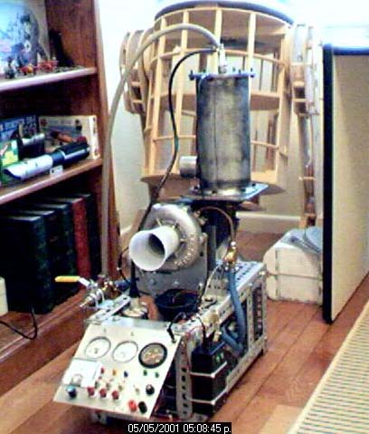
14th April 2001 The engine, with combustor, now almost totally complete. Missing is the air tube that goes from the compressor outlet to the combustor inlet (bottom left of combustor). Visible on top of the combustor are the sparkplug and the gas inlet pipe coming up from the quick shutoff valve with the yellow handle. Please excuse the half finished R2 unit in the background! 
14th April 2001 
11th March 2001 
18th December 2000 Introduction The first question I always get asked is 'Why?' The answer is of course 'Because I can.' The second question I always get asked is 'What does it do?' Well, hopefully that will become clear as you read more. And perhaps at the end you may even understand the answer to the first question too! I first read about gas turbine engines built around ordinary automotive turbochargers several years before I started on my own engine. The few pages I saw back then didn't really explain how things were done in any great detail. Or at least I wasn't convinced they were describing something that I could actually do myself. I mentioned the idea to a few workmates and the general reaction was that you'd be mad to try it. Mad as I am, I lost interest. Recently I happened to again come across web sites describing turbocharger based engines. There seemed to be more people who had tried this and many of them have put together very interesting and informative web pages on how they did it. From the information now available I began to convince myself it was a project I could attempt at home. Here I will give some very basic background information about gas turbines, turbochargers and how one may be used to build the other. This is followed by a description of my own engine and how I am building it. Back to page 1 contentsThe gas turbine What is a gas turbine? A gas turbine is an engine where fuel is continuously burnt with compressed air to produce a stream of hot, fast moving gas. This gas stream is used to power the compressor that supplies the air to the engine as well as providing excess energy that may be used to do other work. The engine consists of three main parts. The compressor, the combustor and the turbine. The compressor usually sits at the front of the engine. There are two main types of compressor, the centrifugal compressor and the axial compressor. The compressor will draw in air and compress it before it is fed into the combustion chamber. In both types the compressor rotates and it is driven by a shaft that passes through the middle of the engine and is attached to the turbine. The combustor is where fuel is added to the compressed air and burnt to produce high velocity exhaust gas. Down the middle of the combustor runs the flame tube. The flame tube has a series of holes in it to allow in the compressed air. It is inside the flame tube that fuel is injected and burnt. There will be one or more igniters that project into the flame tube to start the mixture burning. Air and fuel are continually being added into the combustor once the engine is running. Combustion will continue without the use of the igniters once the engine has been started. The combustor and flame tube must be very carefully designed to allow combustion to take place efficiently and reliably. This is especially difficult given the large amount of fast moving air being supplied by the compressor. The holes in the flame tube must be carefully sized and positioned. Smaller holes around where the fuel is added provide the correct mixture to burn. This is called the primary zone. Holes further down the flame tube allow in extra air to complete the combustion. This is the secondary zone. A final set of hole just before the entry to the turbine allow the remainder of the air to mix with the hot gases to cool them before they hit the turbine. This final zone is known as the dilution zone. The exhaust gas is fed from the end of the flame tube into the turbine. The turbine extracts energy from the exhaust gas. The turbine can, like the compressor, be centrifugal or axial. In each type the fast moving exhaust gas is used to spin the turbine. Since the turbine is attached to the same shaft as the compressor at the front of the engine the turbine and compressor will turn together. The turbine may extract just enough energy to turn the compressor. The rest of the exhaust gas is left to exit the rear of the engine to provide thrust as in a pure jet engine. Or extra turbine stages may be used to turn other shafts to power other machinery such as the rotors of a helicopter, the propellers of a ship or electrical generators in power stations. 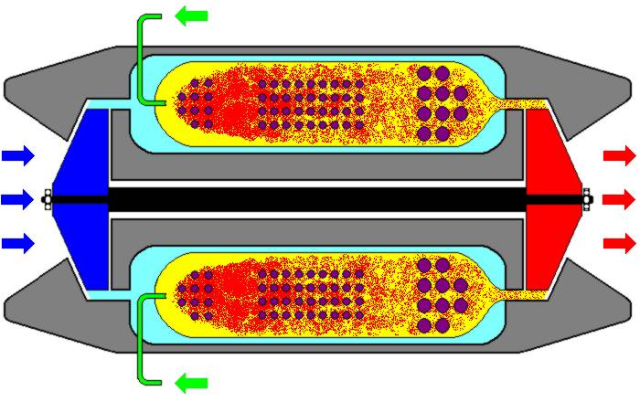
Simplified gas turbine diagram. Cold air is drawn in from the left into the compressor (blue). The compressed air (light blue) then goes into the combustor. From the outside of the combustor the air goes through holes (purple) into the flame tube (yellow). Fuel is injected (green) into the flame tube and ignited. The igniters are not show here. The hot exhaust gas flows from the end of the flame tube past the turbine (red) rotating it as it passes. From there the exhaust exits the engine. The turbine is connected via a shaft (black) to the compressor. Hence as the turbine rotates the compressor rotates with it drawing in more air to continue the cycle. Obviously this is only a simplified view of a gas turbine engine and a working engine is much more complicated. But maybe not too complicated to be built at home..... Back to page 1 contentsThe turbocharger What is a turbocharger? A turbocharger is a device fitted to internal combustion engines to increase power. In a normal car engine the amount of power the engine produces depends on how much fuel is being burnt in the cylinders. In a non-turbocharged engine a mixture of air and fuel is drawn into the engine as the piston moves down in the cylinder. The ideal mixture is 14.7:1 air to fuel (by weight) for gasoline. This is called the stoichiometric ratio. If you always try to maintain this ratio then if you add more air to an engine you must add more fuel. And if you are burning more fuel you will generate more power. The turbocharger is simply a device to force more air into the engine. To increase the amount of air in the engine the turbocharger uses a compressor. The compressor consists of a finned wheel that spins at high speed in a specially shaped housing called a volute. Air is drawn into the center of the compressor wheel and accelerated as it is flung to the outside of the wheel. The volute channels and slows the air which causes its pressure to increase. Increasing the pressure means you can now have more air in a given space, such as the space inside a cylinder. The amount by which the air is compressed is called 'boost'. The compressor wheel must run at very high speeds (up to and over 100000 rpm) to give useful levels of boost. The compressor wheel is connected to one end of a shaft which runs through the central core of the turbocharger. The shaft usually runs in plain bearings which need constant lubrication. Oil under pressure must be pumped through the central core constantly. When it is turning the shaft is essentially 'floating' on a cushion of oil. The oil also helps remove heat generated by friction. Without proper lubrication a turbocharger will very quickly fail. The core of the turbocharger may also contain passages through which cooling water is circulated. At the opposite end of the shaft from the compressor is the turbine wheel. The turbine wheel is also contained in a volute housing but in this case hot exhaust gases from the engine are fed in from the edge of the housing and flow out from the centre of the wheel. The flow of hot gas causes the wheel to accelerate to the very high speeds the compressor needs to provide a lot of boost. Once the gases have passed the turbine wheel they flow through the normal exhaust system of the engine. Because too much boost can actually be damaging to an engine a way of limiting the turbine wheel speed is often needed. One way of doing this is with a wastegate. The wastegate allows the hot exhaust gases to bypass the turbine wheel. Instead of driving the turbine the gases simply flow through an alternate passage in the turbocharger directly into the exhaust. 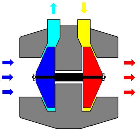
Simplified turbocharger diagram. Cold air is drawn in from the left into the compressor (blue). The compressed air (light blue) then goes exits the turbo and it is fed into the engine. Hot exhaust gas from the engine (yellow) is fed back into the turbo. The hot gas flows past the turbine (red) rotating it as it passes. From there the exhaust exits the engine. The turbine is connected via a shaft (black) to the compressor. Turbochargers come in many different sizes. Many have been used as the basis for home made gas turbine engines. Back to page 1 contentsOn to page 2 contents |
Copyright © 2000 - 2004 Simon Jansen