
June 24th 2007
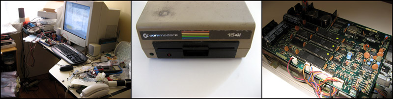
Figure 7. A tidy work space is essential, the 1541 floppy drive and it's circuit board.
As I mentioned one of the geek jokes on Futurama is that Benders brain is using a 6502 processor. The chip was invented in 1975 and was used in many of the early home computers. My first computer was a Commodore Vic 20 back in about 1984 and both this and the later Apple 2s I owned used this processor. I thought it would be interesting to use a real 6502 processor and make my own computer from scratch and use this to make Bender talk somehow. I had previously built for a circuit for an earlier Lightsabre project where a PIC 16C84 microprocessor is used to play samples stored in memory. The processor is used to control a binary counter that simply clocks out data from the memory chip and latches it through to a simple D to A converter to turn it into sound. I decided I could use the same idea but with a 6502 instead of a PIC.
Now a PIC is a modern processor. Basically it is an entire computer on a chip and it needs very few other components to get it do anything useful. A 6502 is old school though. To actually make it do anything you need a lot of support circuitry and other chips. At a minimum you need a clock generator, RAM, ROM and I/O (input-output) as well as a lot of logic 'glue' to make it all work together. I did say this project would be interesting, not simple! The specifics of the 6502 computer and audio board I built deserve their own page which I shall put up soon (with circuit diagrams and code) but here is the basic idea.
When I was researching using the 6502 I came across an interesting fact. The Commodore 64, another very successful early home computer, used a variant of the 6502 (the 6510). Even though the C64 itself doesn't use a 6502 the 1541 floppy drive used with them did. In fact the floppy drive contains a 6502 and all the support circuitry you need to make your own computer. As it happens I happened to have an old 1541 floppy drive sitting under my parents house after someone gave it to me sometime over 10 years ago. I went and rescued it and found it was in pretty good condition. My original aim was to modify and use the drive pretty much as it was but in the end I decided to use the parts (mainly the 6502, the 2016 RAM chip and the 6522 I/O chip) to make my own, smaller single board computer. I am using pretty much the same core circuit as the 1541 drive but with only one I/O chip and with a slightly easier to find ROM chip as the original 2364 EPROM is difficult to get these days.
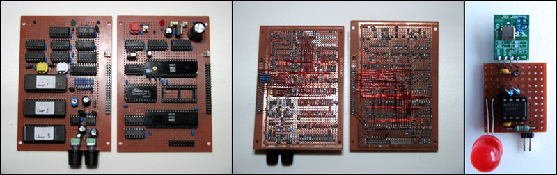
Figure 8. My 6502 based audio and CPU board, wiring side and the wireless transmitter.
Building the computer went very well. I use experimenters strip board with point to point wiring using enameled copper wire. You can get several different types of wire but the one to be used for this is the kind where the red insulation can be burned off with a soldering iron. Unfortunately when I was testing the circuit disaster struck! Having a somewhat messy work area I inadvertently plugged the wrong power supply into my circuit board and immediately sent the CPU, the RAM and the I/O chip off to silicon heaven! The project came to a halt at that point as without the CPU and other chips I couldn't do much. I was going to look on TradeMe, the local auction web site, for a replacement 1541 drive to scavenge parts from but in the end I discovered a nice little site online in the states who supply old chips for people restoring old computers and arcade games - ArcadeComponents.com. I ordered a new CPU, RAM and I/O chip for very, very reasonable prices (actually I ordered two of each in case I had any more 'accidents') and once they arrived I was able to continue.
Once I knew my replacement chips were on the way I started on the audio part of the circuit. I wanted to build this so it would be testable without needing the 6502 computer to drive it. Basically how it works is as follows. I am using old 27C2001 2Mbit x 8 EPROM chips I bought from the local surplus electronics supplier. I am using three of these chips to store audio samples in 8 bit 16kHz raw format. The circuit will support up to 10 audio ROMS but three fitted nicely on the circuit board. Each chip allows me to store around 15 seconds of audio so I have about 45 seconds in total. The processor selects which chip is the one being played from. To get the audio out of the chips I use a binary counter attached to the ROMs address lines. The counter is driven by a 555 timer based clock on the audio board. The processor can control via an AND gate when to send the clock signal through to the counter. The output of the audio ROMs is fed into a latch then into a simple R2R D to A converter. This converts the digital bits into an analogue signal. The signal is fed to a small onboard amplifier attached to an old PC speaker.
By resetting the binary counter and then starting the clock the circuit increments up through the ROM address space clocking out samples one at a time to be converted into sound. If you start addressing at 0 and let it keep clocking it will simply play the entire contents of the chip then loop around to the start again. That would give you 15 seconds of audio in one go. What I wanted to be able to do was play different, shorter samples randomly so Bender can have many things to say. The way I did this is to break the address space into separate spaces or pages. But having the 6502 processor be able to set the top four bits of the binary counter before you start counting you can break each ROMs address space into 16 evenly sized blocks and you can start playing at any one. The top four bits are set on a presetable binary counter which is simply a counter that can be set with a starting value and it will then count up from there rather than zero. To know when to stop playing a sample I encoded a value of 255 into the sample. Some simple logic on the audio board can detect this value (since all 8 data bits are set) and this causes a hardware interrupt back to the processor so it knows to stop playing. To start playing I simply poll an input on the processor I/O board. Samples may span more than one block. I built the audio board in such a way that I could simulate the processor inputs into it and test it in stand alone mode. that way I was able to build and test the audio circuit and be sure it was working before finishing off the 6502 computer.
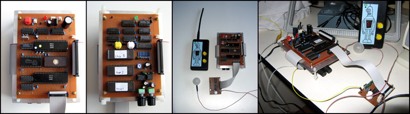
Figure 9. 6502 CPU board, audio board, remote with brain, light and wireless receiver.
Once my new 6502 and other chips arrived I was able to finish building the computer. I had many problems to solve along the way and actually had to buy a new oscilloscope in the end to be able to debug my circuit and code but eventually I got the computer to work. This is now all nicely interfaced with the audio board and controlling it. The code is very simple. It knows the chip and starting location of all the samples stored in the brain. In the end I recorded 15 different Bender sayings from Futurama episodes. The code simply loops around all the starting addresses storing each one one particular memory location. Between storing each value I poll for a input which tells me it is time to start playing. If the input is there the processor simply uses the last starting value it stored and outputs the correct chip selection and starting address bits to the audio board and starts the clock running. While playing other inputs are ignored but the addresses keep looping. When playing stops it simply starts looking for another trigger signal. Because the looping of the 15 addresses is done so quickly you never know quite which address it on when the play is triggered giving a more or less random selection of samples.
To hear the samples stored on each of the chips click below:
Chip_1_8bit.wav (241 kB)
Chip_2_8bit.wav (235 kB)
Chip_3_8bit.wav (251 kB)
The "faith and begorrah" saying on chip two is in memory of my Irish friend Davina. No, she didn't die. Something much worse. She went to Australia!
The triggering is done by a separate circuit board. The simplest trigger is just a push button on this board but I wanted something better than that. I wanted it to be triggered by remote control and in particular with a remote like one they used on the show. In the episode "War is the H Word" a bomb is placed inside Bender that can be activated by a remote control. I bought a very simply ASK transmitter and receiver module which is usually used for small wireless remotes and adapted that to work as a remote control for Bender. The actual remote case has been styled to look similar to the one in the episode. Now, with each press of a button Bender will talk. Holding the buttons down Bender just keeps talking saying random things. Also when the button on the remote is pressed the ball on top of his antenna lights up red. I have provision for two other inputs to trigger the talking. I will probably put a sensor on Benders metal door and use that as one trigger and I am undecided how (or if) I will use the other at the moment. The remote is surprisingly effective and with only simple antennas I was easily getting 20-30m range from it. By the way the place to find out anything about the 6502 and 6502 based projects is here at 6502.org.
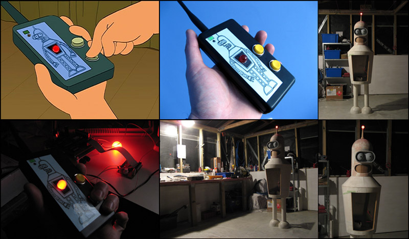
Figure 10. The real remote and mine showing how the remote and antenna light glow. Bender is looking menacing but really he's armless (boom boom)!
July 1st 2007
Finally some progress has been made on Benders arms. Today I used my router circle cutting jig to make small wooden discs to be the ends of the arm and wrist as well as mounting points for the shoulders. The discs are slightly smaller than the diameter of the pool noodle. The shape of the arms is made from half inch copper water pipe. Into one end of each pipe I soldered a 8mm nut. This is the shoulder end which will be attached to the body with a 8mm bolt threaded through from inside the chest. The pipe when then carefully bent using a vice. The pipe does end up kinked and squashed but this doesn't matter as none of that is seen.
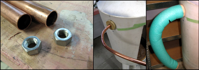
Figure 11. Mounting nuts and pipes, copper arms bent and attached, pool noodle covering.
I then made holes in the centre of two of the wooden discs and hot glued them to the copper pipe. I was then able to slide a length of noodle over the copper tube. I found that the tight bend in the pipe meant I needed to cut V shaped notches into the noodle to get it to bend nicely around the pipe. As the arms will be covered in fibreglass these notches don't matter at all. I covered over them with strips of masking tape. Once the noodle would fit nicely I hot glued another wooden disc to the wrist end of the arms. The noodle is glued on it's ends to each disc. I did a temporary test fitting of the arms and they look great! I still need to make the shoulder fitting which will consist of a wooden disc on the inside and the outside of the body. These will be bolted to each other with the body in between. Through the middle of them will be an 8mm bolt to which the arms threads on. A spring should allow the arms to be rotated and positioned where ever I like. The hands will probably be attached to the end of the arms using strong magnets so they too can be positioned as I like.
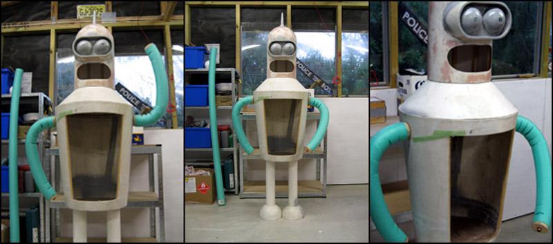
Figure 12. Arms aren't bendable but they are able to rotate into various Bender poses.
I have added the shoulders now. These are simply more cut up polystyrene spheres. These are painted over then covered in fibreglass to form a hard shell. Inside the body I have glued a wooden disc through which goes an 8mm bolt into the end of the arms. There are several washers and a spring (taken from an old fridge compressor) to provide tension on the arms. They can rotate but will stay in whatever position they are put in due to the spring tension.
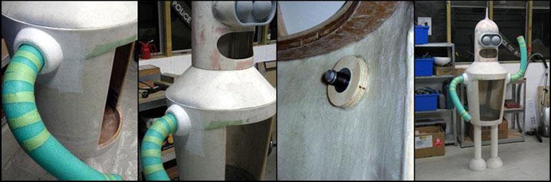
Figure 13. Details of the shoulders and the internal arm fixing bolt and tension spring.
I also did some work in mounting the brain into a unit more suitable for head based installation. The circuit boards are mounted to a red plastic base board. This board has switches and sockets on it. The switches are the main power switch and a push button reset switch. There are sockets for an external power supply as well as a RCA socket to plug the speaker into. On the rear of the mounting board is a four D cell battery holder. The brain can be run on either the plug in power supply or off the battery making it completely portable. The brain and speaker will be mounted (somehow) into the head.
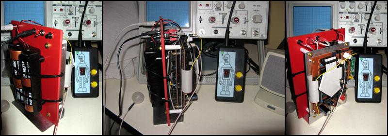
Figure 14. The completed brain with battery supply.
August 5th 2007
No pictures just now but I have started fibreglassing Benders arms and shoulders. I found that painting the polystryene isn't enough. The resin got into the paint and slowly ate the shoulder formers away as the resin hardened. I was hoping the resin would go off before the polystyrene former disappeared and it seems I did manage to get away with it. One shoulder is a little lumpy but nothing some sanding and bogging won't fix. I have also done several layers on one arm as I can only work on one at a time. It will need a lot of sanding and smoothing off as it is tricky fibreglassing over such a curved surface but I am sure it will work out in the end. Unfortunately I have run out of woven cloth which means next weekend another trip to the fibreglass place. One good thing I discovered thought is pool noodle foam is resin poof meaning I didn't have to do anything fancy covering that foam before laying on the fibreglass.
I am also working on drawing up the circuit diagram of the brain and associated circuitry.
August 11th 2007
I did an early morning trip out to New Zealand Fibreglass to get more cloth this morning. If anyone is doing a fibreglass project like this I can recommend them. There is another place closer to me, Nuplex Industries, but they were completely hopeless. I called them and the guy on the phone was utterly useless. So I decided to pop down there to see if I could get better service in person. Nope. I think it was the same utterly useless guy. After ignoring me for 5 minutes he finally came to see what I wanted. I told him what I was doing and asked what he thought would be the best resin to use. He didn't know. I asked what the best cloth to use would be and he recommended some rather thick chopped strand mat. I suspect because that's all they seemed to have. I asked how much resin do you need for a certain amount of cloth. He didn't know. I asked him how much it would cost and he couldn't tell me that either. I think he'd been sniffing too many fumes from the resin spill that seemed to have been left in the middle of the floor. So yes, definitely leave them well alone and go to NZ Fibreglass instead is my advice.
When I got home I did some more on one of the arms and will start the other soon. I need to hold each arm in the vice to be able to lay the glass onto them so I can only work on one at a time. I also drew up part of the circuit diagram for the brain. So far I have only done the CPU board but I shall hopefully finish the audio board soon. This circuit should be pretty close to the finished product but I make no guarantee it will work as drawn. There may be errors in it. I had to do a bit of a brain-ectomy and partially dismantle it to be able to trace out parts of the circuit I hadn't properly documented when I prototyped it.
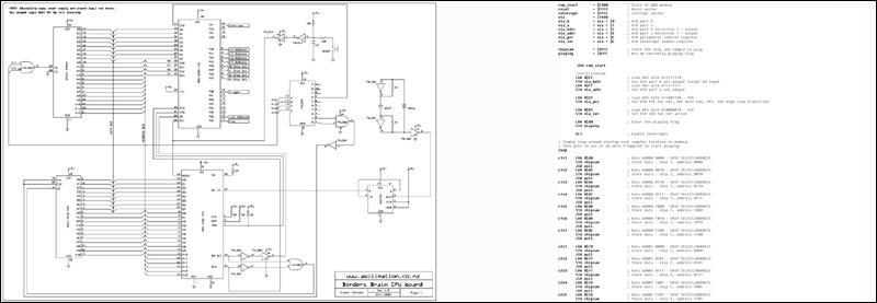
Figure 15. Click on the image to bring up the diagrams and source code.
The audio part of the circuit is now included above
Next page 3Back to page 2