Page 8
Page 1 - Page 2 - Page 3 - Page 4 - Page 5 - Page 6 - Page 7 - Page 8 - Page 9 - Page 10
Page 11 - Page 12 - Page 13 - Page 14 - Page 15 - Page 16 - Page 17 - Page 18 - Page 19
Page 20 - Page 21 - Page 22 - Page 23 - Page 24 - Page 25
December 2005
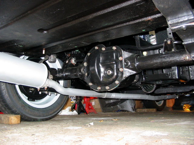
The exhaust all buttoned up. I sprayed it all with high temp paint just to give it a little
more protection from rust, especially where the welded joints are. It took a little bit
of adjustment to get the pipe to the correct shape. I used an oxy-acetylene flame and a
BFH to make the necessary precision adjustments.
December 2005/January 2006
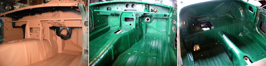
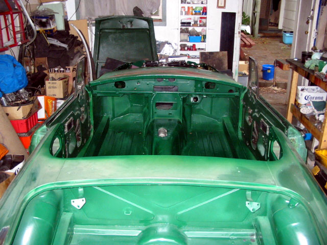
I finally got the interior painted. The first shot shows the anti-rust primer and the black sound
deadening and seam sealing spray I used. This seems to closely match the factory finish and also
helps conceal where I have patched and changed various bits of metalwork. The second shot is the
interior all painted up. I didn't bother to clear coat as I don't need a glossy finish as most of
this area is either covered up with sound deadening, carpets and trim or else is not visible anyway.
I will be so glad when I have my new garage built and I have space. If bloody Auckland City Council
ever get their arses into gear to approve it! Seems it takes them 2-3 months to approve something
that will be built in a week.
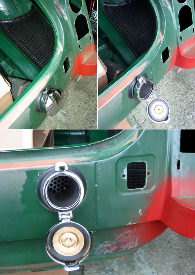
The Monza fuel filler cap in place. I cut a length of the right diameter exhaust pipe and soldered on the
brass threaded ring the filler screws to. At the end of the pipe I also welded on some perforated steel
plate which is there so the fuel can't be easily siphoned out. I am not sure which way up the filler is
supposed to fit but this seems to make most sense. Hopefully it doesn't get in the way of the petrol
pump nozzle. It is easily rotated if need be.
In this picture you can also see the sound deadening I am using. It is heavy, black, tar like pads that
are self adhesive on one side. You cut them to shape then stick them down using a hot air gun to soften
the material so it conforms to the curves and makes the adhesive stick better. I will use these on the
floor pans as well as the firewall.
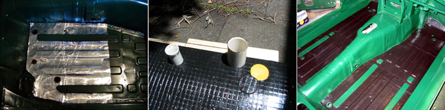
I added sound deadening pads to the floor pans to help reduce rattles and noise. It comes in sheets about 500
by 500mm and so is the exact right width for the floor pans. I needed three sheets per side. To figure out
how to cut them I use a good trick. I make a template from silver building paper first. This is two layers
of silver foil with tar between them. I think it is usually used as insulation under the floors of houses.
I find it is great for making templates for making steel patches or for jobs like this. It is relatively
rigid but it can be shaped then it will hold it's shape quite well. That allows me to curve it as needed
and press it tight into corners. Any holes or corners can be seen by pressing the foil into the edges which
then leave an impression on the foil you can cut around. Once I have the template I traced around it onto
the sound deadening pads and cut them out using a sharp knife. To make the holes I made two cookie cutters
from bits of PVC pipe with the edges filed sharp. I could then put these over the pads then hit them with a
a rubber mallet to punch out perfect holes. These are needed so you don't cover over the drain holes in the
floors. I left the ridges that the seat rails fit over free as well.
January 2006
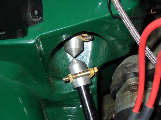
This is how I use the tool I made to adjust the steering rack alignment. The points of the cones match where the
middle of the steering u-joint goes. When the points line up you know the u-joint will not be under any
sideways loading which could shorten it's life, ruin the steering rack oil seal or and make the steering stiff.
I lined them up then bolted the steering rack in position. You then remove the steering wheel and shaft, remove
the tools then attach the u-joint to the shaft. Then you put the steering wheel and column back into place.
Updated: 14 January 2007

Here are the dimensions for the steering alignment cones I made. To make them you do need access to a lathe and a mill.
There were made from aluminium bar stock. The diameter and length aren't critical. The critical dimensions are as
follows. The diameter of the central hole needs to be such that there is a snug fit over the steering shafts without too
much clearance so they cone doesn't move sideways on the shaft. And the distance from the point to the centre line of
milled slot for the 5/16 bolt needs to be exactly the same distance as from the slot on the shafts to the centre point
of the u-joint spider. I milled the slot vertically rather than horizontally so the slot has a curved base to fit the
bolt. The bolt is the same size as used on the u-joint itself. You can see I just used a ruined one I had lying about!
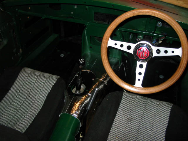
I added some sound deadening to the transmission tunnel. This is also foil backed for heat insulation. Since I had
use small pieces it looked a bit patchy. Being a perfectionist I then added another layer of foil to tidy things
up (even though all of this is hidden under the carpet I still know it's there!). I used a foil windscreen shade
which only cost a couple of dollars. It is foil with a thin foam backing which is perfect to glue into place. It
made everything nice and tidy and of course it adds even more sound and heat insulation. You can also see my MOMO
wheel with the custom centre housing I made from steel, had chromed and added a replica MG badge to. The old,
grotty seats will be going! The only thing I can really get for the car is real leather I guess. Come this far,
might as well go all the way!
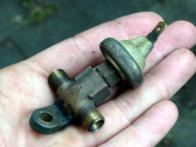
I have no idea what this is or where it goes! I think it might be a oil pressure warning switch? The screw threads do
fit the oil pressure gauge lines perfectly. I can't find it in the Moss catalogue or any of my manuals.
Update: According to people on the MGBBS it is part of the original emissions control equipment and it is a
pressure switch used to operate the anti run on valve. Since I don't have any of that I can leave it out.
Page 1 - Page 2 - Page 3 - Page 4 - Page 5 - Page 6 - Page 7 - Page 8 - Page 9 - Page 10
Page 11 - Page 12 - Page 13 - Page 14 - Page 15 - Page 16 - Page 17 - Page 18 - Page 19
Page 20 - Page 21 - Page 22 - Page 23 - Page 24 - Page 25